Thermal Transfer Barcode & Label Printer CL-S700 U SER'S M ANUAL
CONTENTS Before Operation INTRODUCTION -------------------------------------------------------------------- 3 COMPLIANCE STATEMENT FOR EUROPEAN USERS ----------------------------- 4 FCC COMPLIANCE STATEMENT FOR AMERICAN USERS ----------------------- 4 EMI COMPLIANCE STATEMENT FOR CANADIAN USERS------------------------ 5 ETAT DE CONFORMITE EMI A L’USAGE DES UTILISATEURS CANADIENS ----- 5 IMPORTANT SAFETY INSTRUCTIONS --------------------------------------------- 6 NOTICE -------------------------------------
INTRODUCTION Thank you for purchasing a Citizen CL-series label printer offering high performance printing at up to 10 inches per second on media up to 4.65 inches wide. ❚❚❚ Main Features ❚❚❚ The printer is designed for all day-to-day operations to be accessible from the front of the printer so there is no need to move items near to the printer for access for media loading.
COMPLIANCE STATEMENT FOR EUROPEAN USERS CE marking shows conformity to the following criteria and provisions: Low Voltage Directive (73/23/EEC)/EN60950-1 EMC Directive (89/336/EEC)/EN55022, EN55024, EN61000-3-2 & EN61000-3-3 This product has been tested under EN ISO 7779 and has an acoustic level output no higher than 55db(A). This device is not intended for use at a video workstation in compliance with Bildscharb V.
EMI COMPLIANCE STATEMENT FOR CANADIAN USERS This Class A digital apparatus complies with Canadian ICES-003. This equipment generates and uses radio frequency energy and if not installed and used properly, that is, in strict accordance with the manufacturer's instructions, may cause interference to radio and television reception.
IMPORTANT SAFETY INSTRUCTIONS • Read all of these instructions and save them for later reference. • Follow all warnings and instructions marked on the product. • Unplug this product from the wall outlet before cleaning. Do not use liquid or aerosol cleaners. Use a damp cloth for cleaning. • Do not use this product near water. • Do not place this product on an unstable cart, stand or table. The product may fall, causing serious damage to the product.
NOTICE • Before use, be sure to read this manual. And keep it handy for reference when needed. • The contents of this manual may change without prior notice. • Reproduction, transfer, or transmission of the contents of this manual without prior consent is strictly prohibited. • We are not liable for any damage resulting from the use of the information contained herein, regardless of errors, omissions, or misprints.
SAFETY INSTRUCTIONS which must be strictly observed ! • To prevent personal injury or property damage, the following shall be strictly observed. • The degree of possible injury and damage due to incorrect use or improperly following instructions is described below. Warning Indicates a situation which, if not observed and handled properly, could result in death or serious injury. Caution Indicates a situation which, if not observed and handled properly, could result in injury.
General Precautions Caution • Prior to operation, read the safety instructions carefully and observe them. • Do not drop or put foreign matter such as clips and pins into the printer. This may cause problems. • Be careful when moving or carrying the printer. Dropping the printer may cause injury or property damage. • Make sure if you open the top cover, it is opened all the way. If only partially open, the cover could slam shut, possibly causing injury.
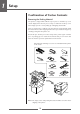
1 Setup Confirmation of Carton Contents Removing the Packing Material The printer is shipped with adhesive tape in place to hold the top cover closed. Simply remove the two pieces of tape on either side of the top cover. Then simply open the cover by lifting up and tipping it backwards. There is another strip of adhesive tape that must be removed which holds the mechanism closed for shipping. Remove the tape and attached paper by carefully peeling from the plastic case.
Setup Caution • Be careful when moving or carrying the printer and when taking the printer out of the carton. The printer may cause injury or property damage if dropped. Be sure to grip the printer housing firmly when taking it out of the carton. Do not grip the printer by the foam packing material which may break, causing the printer to drop. • When opening the cover, open it all the way. If only part way open, the cover could slam shut, possibly causing injury.
1 Setup Part Names and Functions 3 2 1 1 Ribbon holder It is used to attach the ribbon and paper core. 2 Media holder guide This guide is moved horizontally to match the media size. The guide can be sliding it from the holder bar. 3 Media holder bar The media is supported by the media holder bar when installed in the printer.
Setup Part Names and Functions 1 6 2 3 Media Thickness Adjustment (p.49) 4 5 1 Media thickness adjustment screw It is adjusted to match the thickness of the media. 2 Media width adjustment indicator Media Width Adjustment (p.50) 3 Media width adjustment knob It is adjusted to match the width of the media. 4 Media thickness adjustment indicator 5 Head open lever The head unit can be raised to install media by pushing this lever. It locks the head unit during printing.
1 Setup Part Names and Functions 1 2 3 8 5 7 4 6 1 Thermal printhead This is the printhead. Avoid touching this with your fingertips and leaving grease or dirt on the printhead surface. 2 Sensor arm The media can be installed by raising this arm. The media can be held in place by lowering this arm. Sensor Adjustments and Calibration (p.46) 3 Adjustable (rear) sensor Installing the Media (p.25) 4 Fixed media sensor Detects the label or tag position. This sensor is switched “on” by default.
Setup Part Names and Functions Operation Panel 1 2 POWER 4 ERROR 3 STOP 6 FEED PAUSE 5 MENU LED Functions (p.21) 7 1 LCD display This displays the operational status of the printer. 2 POWER LED This is lit when the printer power is on. (green) 3 ERROR LED This is lit or flashes when the printer is in an alarm or error status. (orange) 4 FEED key This key feeds the media to the top of the next label or form. Normal Operating Mode (p.20) 5 PAUSE key This temporarily stops printing.
1 Setup Part Names and Functions Rear View 4 1 2 5 3 Parallel Interface (p.63) 1 Parallel interface (Centronics parallel or IEEE1284) This receives parallel transmission of data from a host computer. Serial Interface (p.61) 2 Serial interface (RS232C) This receives serial transmission of data from a host computer. USB Interface (p.66) 3 USB interface This receives USB transmission of data from a host computer. 4 Heat air opening It allows warm air to vent from the printer.
Setup Connection to Power 1. The power switch is located on the front of the printer recessed below the control panel. Check that the power switch is turned OFF. 2. Insert the power cord in to the inlet on the printer. 3. Insert the plug of the power cord in the AC outlet. Power Switch AC Outlet Power Cord Inlet Caution Use an AC outlet that accepts a three-pronged plug. Otherwise, static electricity may be generated and there will be danger of electric shock.
1 Setup Connection to a Computer This product has three interfaces that can be used to receive printing data: a serial port (RS232C), parallel port (IEEE1284, Non-L. P. S.), and a USB port (USB1.1). An optional internal network interface can be added by your dealer. To connect the cable, proceed as follows: 1. Turn OFF both power switches of the printer and the computer. 2.
2 Printer Operation Printer Operation Power ON/OFF Turning on the power 1. The power switch is conveniently located at the front of the printer for easy access during normal operation. It is in the recess underneath the control panel so it cannot be accidentally operated by mistake. 2. The POWER LED is lit. Operation Panel POWER ERROR FEED Power Switch Turning off the power 1. Turn off the power switch of the printer. 2. The POWER LED goes off.
2 Printer Operation Normal Operating Mode Menu Setup Mode (p.31) When the power is turned on, the printer enters normal operating mode. The control keys activate the following functions. On Line Ready POWER ERROR 2 FEED STOP PAUSE 3 1 MENU 4 1 PAUSE key: Temporarily pauses printing • When this key is pushed once, the LCD indicates "Pause" and the printer temporarily pauses. • When it is pushed during printing, the printer pauses after the label currently being printed is issued.
Printer Operation Normal Operating Mode LED Functions 1 POWER LED It lights up when printer power is turned on. (green) 2 ERROR LED 1 2 POWER ERROR FEED STOP PAUSE This is lit or flashes when the printer is in error status. (orange) MENU Table of Alarm and Error Indications In addition to normal operating mode, when an abnormal condition is detected in the printer, an alarm sounds and ERROR LED either lights up or flashes to indicate the type of error. The LCD indicates the error message.
Printer Operation Setting the Media Media Sizes The position of label and tag media is sensed by either a transparent sensor or a reflective sensor. Transparent sensor: Detects the gaps between label media and notches of tag media Reflective sensor: Detects the black mark Size of media Continuous media Label media E C B A Notch detection Label Black mark detection L I K Label Printable area N H G D M Black mark OD value:1.
Printer Operation Setting the Media When Using Front Sensors A B C D E F G H I J K L M N Menu Setting Table (p.37) Label width Liner width Left end of label Gap between labels Label length Label pitch Liner thickness Media thickness Right end of notch Left end of notch Notch length Right end of black mark Left end of black mark Black mark width Minimum value mm (in) Maximum value mm (in) 7.62 (0.3) 118.00 (4.65) 25.40 (1.0) 118.00 (4.65) 0 (0) 2.54 (0.10) 2.54 (0.10) 812.80 (32.00) 6.35 (0.25) 812.
2 Printer Operation Setting the Media Installing the Media 1. Push the large blue head-open lever to release the head unit, and then lift the sensor arm by hand as shown the right side drawing below. Head unit Sensor arm open lever Sensor arm Large blue-head open lever Media Sizes (p.22) 2. Firstly, slide the two black plastic parts of the media holder assembly together. Ensure correct alignment of the guide with the bar as it can only be installed in one direction. 3.
Printer Operation Setting the Media 4. Set the media roll and media holder in to the printer as shown above. It is advisable to pull a length of media forwards and through the mechanism ready for later positioning. 5. Move the media roll so it is touching the left side of the housing. Then slide the black movable media guide so it is touching the media on the right side. Note: Do not try to hold the media too tightly with these guides as it will cause the printer to jam during printing. 6.
2 Printer Operation Setting the Ribbon The following kinds and sizes of ribbons can be used. Types ...................................................... Inside wound and outside wound ribbon Max. ribbon width ............................... 114.0 mm (4.50 inch) Min. ribbon width ................................ 25.4 mm (1.00 inch) Max. ribbon length .............................. 450.0 m (1,476 ft) Max. roll diameter ............................... 86.5 mm (3.40 inch) Inner diameter of the paper core ....
Printer Operation Setting the Ribbon 3. Push the large blue head-open lever to release the head unit. Pull out the ribbon from the bottom of the head unit to the ribbon winding side. 4. Using tape etc., fix the ribbon that you have pulled out on the ribbon holder on which the paper core has been set and wind it on the ribbon holder. Winding side ribbon holder 5.
2 Printer Operation Setting the Ribbon Adjusting the Ribbon (p.51) 6. Lower the head unit back down to the closed position. Push the head close knob firmly to close and lock the mechanism. The mechanism is only locked correctly when you head a “click”. If the ribbon is wrinkled, push the FEED key until the wrinkles disappear. If the wrinkles do not disappear or if it slips, perform ribbon tension adjustment and media width adjustment. See “Chapter 3 Printer Adjustments” for these adjustment methods.
Printer Operation Mode Settings Operation Panel (P.15) Turning on the power while pressing keys in the following combinations starts various functions. Mode Key operation HEX dump mode Turning power on while pushing the STOP key. Self print mode Turning power on while pushing the FEED key. Menu list print mode and Menu setup mode Turning power on while pushing the MENU key. HEX Dump Mode When using label media Turn on printer power while pushing the STOP key.
2 Printer Operation Mode Settings Self Print Mode Performing a self test print is an easy way to check on the state of printer settings and printing quality. Install the media as explained in “Installing the Media” and then operate the printer as follows. Setting the Media (P.22) Case of label media Turn on printer power while pushing the FEED key. When the LCD indicates "Self Print Mode" and "Label Media", release the FEED key.
Printer Operation Mode Settings Menu Setup Mode If the MENU key is pressed while the printer is in the On Line Ready state, the printer enters menu setup mode. In this mode, the printer's configuration can be changed using the operation panel. During menu setting mode, the LCD indicates the current menu settings and the key function.
2 Printer Operation Mode Settings Example of changing a menu This is an explanation of the method of changing the set value of print darkness from “12” to “14” in a case where the main menu is “Page Setup” and the sub menu is “Print Darkness”. 1. Entering Menu Setup Mode. Ensure LCD displays “On Line Ready”. Then press the MENU key to enter ‘menu setup mode’ where the printers settings can be changed or confirmed. Main Menu Page Setup Exit On Line Ready POWER Enter The current main menu is displayed.
Printer Operation Mode Settings 2. Entering Sub menu. Press the 3 key. The currently set item, “Print Speed”, is displayed. Page Setup Print Speed Exit Enter The following are the functions of each key. 5 key: displays the previous sub menu ∞ key: displays the next sub menu 3 key: displays the values set by the selected sub menu 2 key: returns to the main menu 3. Selecting “Print Darkness” from the sub menu. Press the ∞ key one time to display “Print Darkness”. It is the second item within “Page Setup”.
2 Printer Operation Mode Settings 6. Save the changed value permanently. Unless you perform the following save operation, the new setting value will be lost when you turn off the printer. To Save Changes 1 Press the 2 key twice to display the message “Save Settings No-Discard”. Save Settings No-Discard Exit 2 Press the 5 key or the ∞ key to display the message “Save Settings Yes-Save”. Save Settings Yes-Save Exit 3 Press the 3 key.
Printer Operation Mode Settings Example of changing a menu (p.32) Printing a List of Settings You can get a list of the configuration settings in two ways: - Press MENU key whilst turning the printer on. The Power LED flashes and “Print Settings” is displayed on the LCD. After printing, the printer will enter Menu Setup Mode. - You can access the configuration print via the “Test Mode, Print Pattern, Current Config” from the setup menu.
2 Printer Operation Mode Settings Global Configuration Sets The printer can store three sets of configuration settings that can be recalled quickly and easily. Each “Config Set” (1, 2 or 3) can contain completely different configuration settings for all menu parameters. For example, “Config Set 1” could be configured for 5 ips print speed, thermal transfer labels, print darkness 18. “Config Set 2” next could be 8 ips continuous card media with black mark, print darkness 12.
Printer Operation Mode Settings [Datamax Emulation] Menu Setting Table Page Setup Menu - allows you to change settings related to the media or print quality. System Setup Menu - allows you to change settings for the printer hardware and basic control systems. After Print Menu - changes how the printer reacts after the label has been printed. Interfaces - changes interface parameters such as baud rate.
2 Printer Operation Mode Settings [Datamax Emulation] Top Menu After Print Sub Menu Default Menu Remarks Metric/Inch [Metric/Inch Sel] Inch Inch mm Sets the units. Max Media Length [Max Media Len] 10.00 inch 254.0 mm 1.00 to 50.00 inch 25.4 to 1270.0 mm Sets the maximum media length. Settings Lock Off On Off Prevents a command changing the set value. Keyboard Lock Off On Off Prevents a change by a key operation.
Printer Operation Mode Settings [Datamax Emulation] Top Menu Interfaces Machine Information [Machine Info] Test Mode Sub Menu Default Menu Remarks Menu Key Action Enters Menu Enters Menu Repeat Last Set Repeat Last One Sets the menu key action. Enters Menu: Enters the menu setup mode. Repeat Last Set: Repeats the number of copies. Repeat Last One: Last one is issued only for the final page. In the case of a count, afterwards, only last one is issued.
2 Printer Operation Mode Settings [Datamax Emulation] Top Menu Sub Menu Default Menu Remarks Factory Default No Yes No Initializes the set values of the configuration set to the state when the unit was shipped from the factory. Hex Dump No Yes No Sets the hex dump mode. Serial Monitor – – Displays the state of the serial interface. Auto Calibration [Auto Cal] See Through See Through Reflect Executes the calibration of the sensor.
Printer Operation Mode Settings [Zebra Emulation] 7 Zebra Emulation Top Menu Sub Menu Default Menu Page Setup Print Speed 7 IPS 2 to 10 IPS Printing speed setting. Print Darkness 12 00 to 30 Adjusting print darkness. Darkness Adjust [Darkness Adj] 00 -10 to 10 Fine adjustment of darkness commands. Print Method TT TT (Thermal Transfer) Selection of Thermal Transfer (ribbon) or DT (Direct Thermal) Direct Thermal. Continuous Media Length [Cont Media Len] 4.00 inch 101.6 mm 0.25 to 32.
2 Printer Operation Mode Settings [Zebra Emulation] Top Menu After Print Interfaces Sub Menu Default Menu Remarks Emulation Select [Emulation Sel] DM4 DM4 DMI DPP ZPI2 Selects DataMax/Zebra compatibility DM4: DataMax 400 DMI: DataMax IClass DPP: DataMax Prodigy Plus ZPI2: Zebra 2844Z Emulation Auto Detect [Emulation Auto] On On Off Setting emulation (Datamax/Zebra) auto detection. AutoConfigure [Auto Config] On On Off Automatically configures optional devices. On ....
Printer Operation Mode Settings [Zebra Emulation] Top Menu Machine Information [Machine Info] Test Mode Sub Menu Default Menu Remarks RS-232C Parity None None Odd Even Setting the communication parity for the serial interface. RS-232C Length 8 bits 8 bits 7 bits Setting the character length for the serial interface. RS-232C Stop bit [RS-232C Stopbit] 1 bit 1 bit 2 bits Setting the stop bit for the serial interface.
2 Printer Operation Quick Setup of the Print Method Menu Setup Mode (p.31) The print method (thermal transfer method/direct thermal method) can be set using operation panel in addition to menu setting mode. Caution Be sure to always shut off the operation of print before changing a setting. You cannot change a setting during printing (including pause). Setting method Keep the MENU key held down.
Printer Operation Emulation Auto-Detection Menu Setup Mode (p.29, p38, p42) Ordinarily emulation switching is conducted in the Menu Setup mode. However, switching can also be conducted using the Emulation AutoDetection function outlined below. The following message is displayed on the LCD when the Zebra emulation (ZPI2) command is detected during Datamax emulation. ZPI2 detected. Switch emulation ? No Yes By selecting “Yes” the printer will reboot and automatically switch to ZPI2 emulation.
3 Printer Adjustments Sensor Adjustments and Calibration The sensing level of both the transparent (see thru) and reflective sensors is adjusted separately and independently. Firstly, the sensor type must be selected using the Sensor Method Selection shown below. Then the adjustment and calibration of the sensor can be made. The front sensor or adjustable sensor is selected using the Adjustable sensor on the sub menu that is in Page Setup on the main menu. (See “Chapter 2. Printer Operation”).
Printer Adjustments Sensor Adjustments and Calibration Adjusting the Transparent sensor Installing the Media (p.24) Quick Sensor Selection Method (Transparent ↔ Reflective) (p.46) 1. The transparent sensor is selected. 2. Install only the liner media (label backing paper) with the label media removed so that it will pass between the platen roller and the media sensor. (Be careful that media with black marks does not pass the media sensor.) Then close the sensor arm and the printhead.
3 Printer Adjustments Sensor Adjustments and Calibration Adjusting the Reflective sensor Quick Sensor Selection Method (Transparent ↔ Reflective) (p.46) 1. The reflective sensor is selected. 2. With the reflective sensor selected, install the label media so that it is between the platen roller and the media sensor. Be careful that black mark and media gap do not pass the media sensor. Then close the sensor arm and the printhead. Label Black mark Liner media Bottom sensor 3.
Printer Adjustments Media Thickness Adjustment Installing the Media (p.24) The printer is already factory-set to the requirements of proper print quality while using the recommended labels. If the print quality is inferior because of the different type of media, adjust the printhead position in the following manner: Self Print Mode (p.30) When using standard labels, or thermal media 1.
3 Printer Adjustments Media Width Adjustment Installing the Media (p.24) Self Print Mode (p.30) The printer is already factory-set to the value of media width: 112 mm (4.4 in). When you use narrow media, adjust the printhead pressure in the following: 1. Looking in at the check window on the upper frame, align the mark (the left end of white plastic) with the width of media by turning the media width adjustment knob. (The printhead must be closed.) 2.
Printer Adjustments Adjusting the Ribbon Setting the Ribbon (p.26) Ribbon tension in this printer is already adjusted for the recommended ink ribbon and media and is very tolerant to different types of media. However, it may slip due to imperfect combinations of ribbon and media and it is possible that you will see a “Ribbon End” message even though the ribbon is not finished. This is more likely to happen with narrow width ribbons, especially those less than 50mm (2 inches).
3 Printer Adjustments Adjusting the Ribbon 2. Easy-to-slip ribbon and media If a message ‘Ribbon Out’ is shown, set the mark on the feeding section to LOW by turning the adjust-screw. Winding section TENSION Feeding section STANDARD LOW TENSION STANDARD LOW SUPER LOW 3. Especially-easy-to-slip ribbon and media If a message ‘Ribbon Out’ is still shown, although Step 2 has been performed, set the mark on the feeding section to SUPER LOW by turning the adjust-screw.
Printer Adjustments Moving the Adjustable Sensor Operating procedure Menu Setting Table (p.37) Ensure the adjustable sensor is selected. Measure your required detection position beforehand, using the scale on the upper guide rail. Move the adjustable sensor to the required detection position by tuning the adjustable knob; it is useful to align the yellow mark on the top of the adjustable sensor with the scale showing the required detection position.
3 Printer Adjustments Cleaning Wipe off any foreign matter such as media dust, dirt and adhesive substances built up around the printhead and platen with the head cleaning pen (head cleaner) provided, and use a soft cloth soaked in ethyl alcohol for the platen etc. It is particularly important to clean the thermal printhead after printing on thermal media for long periods, which will guarantee the print quality and extend the life of the thermal printhead.
4 Troubleshooting Troubleshooting This chapter explains corrective actions taken when the printer malfunctions or when an error message is displayed. Items to check when a malfunction occurs When the printer malfunctions during operation, take corrective action with reference to the following table. If the corrective action does not solve the problem, consult with the service personnel at the dealer where you purchased the printer. Connection to Power (p.
4 Troubleshooting Indication The printer is not printing neatly. Setting the Ribbon (p.26) Media Thickness Adjustment (p.49) Media Width Adjustment (p.50) Installing the Media (p.24) Setting method (p.26) Cleaning (p.54) The printing position changes. Check 4) Is the thermal printhead dirty? Is a label stuck to the head.
Appendixes Appendixes Specifications Item Printing Description Printing method Resolution Thermal transfer/Direct thermal Main scanning line density: 203 dots/inch (8 dots/mm) Sub- scanning line density: 203 dots/inch (8 dots/mm) Head 864 dots (printable dots: 832 dots) Printing speed Print mode Media Ribbon Max. print width 104 mm 4.1 inch Max. print length 812.
Appendixes Specifications Item Description Bar code One-dimension (for Datamax emulation) • Code 3 of 9 • UPC-A • UPC-E • EAN-13 (JAN-13) • EAN-8 (JAN-8) • Interleaved 2 of 5 • Code 128 • HIBC (Modulus 43-used code 3 of 9) • Codabar (NW-7) • Int 2 of 5 (Modulus10-used Interleaved 2 of 5) • Plessey • Case Code • UPC 2DIG ADD • UPC 5DIG ADD • Code 93 • Telepen • ZIP • UCC/EAN128 • UCC/EAN128 (for K-MART) • UCC/EAN128 Random Weight • FIM Bar code (for Zebra emulation) Two-dimension UPS Maxi Code, PDF-41
Appendixes Specifications Item Media detection sensors Description Transparent sensor Detects media gap between labels, notches on tags, and media out Reflective sensor Detects reflective mark on back of media and media out Label peeling sensor*1 Communication interfaces Communication interface options Parallel*8 IEEE1284 (compatible, Nibble, ECP mode) Serial 2400 4800 9600 19200 38400 57600 115200bps USB FULL Speed USB1.
Appendixes Item Description Weight Approx. 13.3 kg (29.3 lb.) Accessories Test label media, Test ribbon, CD-ROM (User’s Manual), Quick start guide, Head cleaner, Power cord, Media holder bar and Media holder guide, Ribbon holder, Paper core Option Auto-cutter unit, Peeler unit and Ethernet interface board *1, *2: *3: *4. *5: *6: *7: *8: Options can be separately purchased. When a media pitch of less than 1 inch is used, activate the "Small Label Printing" setting in the "Printing Setting.
Appendixes Interfaces This printer is connected to a computer and prints according to commands sent from the computer. There are three types of computer interfaces, and these are connected to devices suited to each type of interface. The printer can also be connected to a computer by the optional Ethernet.
Appendixes Interfaces XON/XOFF Protocol Requirements to output X-ON code • Communication is possible when the power is on. • When the receive buffer has less than 128 bytes available, XOFF code is output, then the receive buffer has at least at least 1024 bytes available.
Appendixes Interfaces Parallel Interface Specifications Transmission mode 8-bit parallel data Receive buffer size 16K bytes Transmission modes Compatible mode It is an asynchronous forward direction of the byte width (from host to printer) channel, and the interface line of the data is operated in accordance with signal line definitions of Centronics. NIBBLE mode Nibble mode is asynchronous reverse channel communication with data transmission controlled by the host computer.
Appendixes Interfaces Parallel port status signals when an error occurs The status of a signal line will not be changed in bi-directional mode such as nibble or ECP mode.
Appendixes Interfaces [While receiving INIT signal] Min. 10 to 15µsec *Init BUSY *Ack *Fault SELECT Note: If the *Init signal does not have width of 10 to 15µsec or more, it cannot act as an Init signal. If it is lower, the *Init signal is ignored. BUSY starts up when the *Init signal is perceived. Relation of the timing of the BUSY signal and the *ACK signal [Center – ACK] BUSY *ACK Approx.
Appendixes Interfaces USB Interface Specifications Standards Complies with Universal Serial Bus Specification Transmission speed Compatible with 12Mbps (full speed) transmission Receive buffer 16K bytes Connector DUSB DUSB-BRA42-T11(DDK) Signal line and pin arrangement Pin No.
Appendixes Replacing the Interface Board Caution Always turn off the power to the printer before replacing the interface board. Do not pull it out with unnecessary force. This will cause an accident. Replacement Method 1. Remove the screws (2) that anchor the bracket of the interface board then pull the interface board towards you. When you do this, be careful not to perform any unreasonable operations that will damage the connecting cable and do not pull the cable too much.
Appendixes Replacing the Interface Board 3. Insert the interface board into the printer so that the connecting cable does not catch on the printer, then use the screws (2) that you removed to anchor the bracket.
363 Van Ness Way, Suite 404 Torrance, CA 90501. USA Tel: (310) 781-1460 Fax:(310) 781-9152 http://www.citizen-systems.com Mettinger Strasse 11 Park House, 643-651 Staines Road D-73728, Esslingen Feltham, Middlesex, TW14 8PA Germany United Kingdom Tel: +49 (0) 711 3906 420 Tel: +44 (0) 20 8893 1900 Fax:+49 (0) 711 3906 405 Fax: +44 (0) 20 8893 0080 http://www.citizen-europe.com 6-1-12, Tanashi-cho, Nishi-Tokyo-shi Tokyo, 188-8511. Japan Tel: +81 (0) 42 468 4608 Fax:+81 (0) 42 468 4996 http://www.