USER'S MANUAL Thermal Transfer Barcode & Label Printer CLP-621
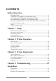
CONTENTS Before Operation INTRODUCTION -------------------------------------------------------------------- 3 COMPLIANCE STATEMENT FOR EUROPEAN USERS ----------------------------- 4 FCC COMPLIANCE STATEMENT FOR AMERICAN USERS ----------------------- 4 EMI COMPLIANCE STATEMENT FOR CANADIAN USERS------------------------ 5 ETAT DE CONFORMITE EMI A L’USAGE DES UTILISATEURS CANADIENS ----- 5 Important Safety Instructions ------------------------------------------------------- 6 Notice ---------------------------
INTRODUCTION Thank you very much for purchasing Citizen's thermal transfer barcode & label printer Model CLP-621 that offers high performance printing at 4 inches per second on 4.1 inch media at very low cost. ❚❚❚ Main Features ❚❚❚ This printer can be used for high-speed high-quality printing thanks to its direct thermal method and thermal transfer method that use a line thermal printhead together with its 32 bit RISC CPU and its 'history control IC'.
COMPLIANCE STATEMENT FOR EUROPEAN USERS CE marking shows conformity to the following criteria and provisions: Low Voltage Directive (73/23/EEC)/EN60950-1 EMC Directive (89/336/EEC)/EN55022, EN55024, EN61000-3-2 & EN61000-3-3 FCC COMPLIANCE STATEMENT FOR AMERICAN USERS This equipment has been tested and found to comply with the limits for a Class A digital device, pursuant to Part 15 of the FCC Rules.
EMI COMPLIANCE STATEMENT FOR CANADIAN USERS This Class A digital apparatus complies with Canadian ICES-003. This equipment generates and uses radio frequency energy and if not installed and used properly, that is, in strict accordance with the manufacturer's instructions, may cause interference to radio and television reception.
Important Safety Instructions • Read all of these instructions and save them for later reference. • Follow all warnings and instructions marked on the product. • Unplug this product from the wall outlet before cleaning. Do not use liquid or aerosol cleaners. Use a damp cloth for cleaning. • Do not use this product near water. • Do not place this product on an unstable cart, stand or table. The product may fall, causing serious damage to the product.
Notice • Before use, be sure to read this manual. And keep it handy for reference when needed. • The contents of this manual may change without prior notice. • Reproduction, transfer, or transmission of the contents of this manual without prior consent is strictly prohibited. • We are not liable for any damage resulting from the use of the information contained herein, regardless of errors, omissions, or misprints.
SAFETY INSTRUCTIONS which must be strictly observed ! • To prevent personal injury or property damage, the following shall be strictly observed. • The degree of possible injury and damage due to incorrect use or improperly following instructions is described below. Warning Indicates a situation which, if not observed and handled properly, could result in death or serious injury. Caution Indicates a situation which, if not observed and handled properly, could result in injury.
General Precautions Caution • Prior to operation, read the safety instructions carefully and observe them. • Do not drop or put foreign matter such as clips and pins into the printer. This may cause problems. • Be careful when moving or carrying the printer. Dropping the printer may cause injury or property damage. • Make sure if you open the top cover, it is opened all the way. If only partially open, the cover could slam shut, possibly causing injury.
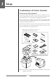
1 Setup Confirmation of Carton Contents Removing the Packing Material The printer is shipped with adhesive tape in place to hold the top cover closed. Simply remove the two pieces of tape on either side of the top cover. Then simply open the cover by lifting up and tipping it backwards. There is another strip of adhesive tape that must be removed which holds the mechanism closed for shipping. Remove the tape and attached paper by carefully peeling from the plastic case.
Setup Caution • Be careful when moving or carrying the printer and when taking the printer out of the carton. The printer may cause injury or property damage if dropped. Be sure to grip the printer housing firmly when taking it out of the carton. Do not grip the printer by the foam packing material which may break, causing the printer to drop. • When opening the cover, open it all the way. If only part way open, the cover could slam shut, possibly causing injury.
1 Setup Part Names and Functions Inside the printer 1 2 3 4 5 Setting the Ribbon (p.26) 1 Ribbon winding selection switch This switch allows selection of inside-wound ribbons (also known as "ink in") and outside wound ribbons ("ink out"). Remember, the inked surface should be facing AWAY from the printhead surface! • To use an inside wound ribbon, push the switch up. • To use an outside wound ribbon, push the switch down.
Setup Part Names and Functions 1 4 2 5 3 6 7 Ribbon Tension Adjustment (p.44) 1 Front (winding side) ribbon tension adjustment knob Ribbon Balance Adjustment (p.45) 2 Front (winding side) ribbon left-right balance adjustment knob Media Width Adjustment (p.43) 3 Media width adjustment dial Ribbon Tension Adjustment (p.44) 4 Back (feeding side) ribbon tension adjustment knob Ribbon Balance Adjustment (p.
1 Setup Part Names and Functions 1 2 3 -1 4 -1 6 7 5 3 -2 4 -2 8 1 Thermal printhead This is the printhead. Avoid touching this with your fingertips and leaving grease or dirt on the printhead surface. 2 Sensor arm The media can be installed by raising this arm. The media can be held in place by lowering this arm. Setting sensor positions (p.24) Sensor Adjustments (p.39) 3 Upper sensor (3-1) and bottom sensor (3-2) Installing the Media (p.
Setup Part Names and Functions Operation Panel 1 2 3 4 5 7 6 8 LED Functions (p.21) 1 POWER LED This is lit when the printer power is on. (green) 2 PRINT LED This is lit when the printer is able to print. (green) 3 CONDITION LED This is on when selecting settings. (orange) 4 ERROR LED This is lit or flashes when the printer is in an alarm or error status. (red) Normal Operating Mode (p.20) 5 PAUSE key This temporarily stops printing.
1 Setup Part Names and Functions Rear View 1 2 3 4 5 Serial Interface (p.52) 1 Serial interface (RS232C) This receives serial transmission of data from a host computer. Parallel Interface (p.54) 2 Parallel interface (Centronics parallel or IEEE1284) This receives parallel transmission of data from a host computer. USB Interface (p.57) 3 USB interface This receives USB transmission of data from a host computer. Power ON/OFF (p.19) 4 Power switch The is the power switch for the printer.
Setup Connection to Power 1. Check that the power switch to the printer is turned OFF. 2. Connect the connector of the power cord to the power cord inlet on the printer. 3. Insert the plug of the power cord in the AC outlet. Power Switch AC Outlet Power Cord Inlet Caution Use an AC outlet that accepts a three-pronged plug. Otherwise, static electricity may be generated and there will be danger of electric shock.
1 Setup Connection to a Computer This product has three interfaces that can be used to receive printing data: a serial port (RS232C), parallel port (IEEE1284, Non-L. P. S.), and a USB port (USB1.1). An optional internal Ethernet or Wireless LAN port can be added by your dealer. With the exception of a wireless LAN connection, an interface cable is necessary to connect the printer to a computer. To connect the cable, proceed as follows: 1. Turn OFF both power switches of the printer and the computer. 2.
2 Printer Operation Printer Operation Power ON/OFF Turning on the power 1. Turn on the power switch on the back of the printer. 2. The POWER and PRINT LED are lit. Operation Panel Power Switch Turning off the power 1. Turn off the power switch on the back of the printer. 2. The POWER and PRINT LED go off.
2 Printer Operation Normal Operating Mode Menu Setup Mode (p.31) When the power is turned on, the printer enters normal operating mode. The control keys activate the following functions. 1 3 2 4 1 PAUSE key: Temporarily pauses printing • When this key is pushed once, the PRINT LED turns off and the printer temporarily pauses. • When it is pushed during printing, the printer pauses after the label currently being printed is issued.
Printer Operation Normal Operating Mode LED Functions 1 1 POWER LED It lights up when printer power is turned on. (green) 2 2 PRINT LED 3 This is lit when the printer is able to print. (green) 4 3 CONDITION LED This is on when selecting settings. (orange) 4 ERROR LED This is lit or flashes when the printer is in error status.
Printer Operation Setting the Media Media Sizes The position of label and tag media is sensed by either a transparent sensor or a reflective sensor.
Printer Operation Setting the Media Installing the Media 1. Push the large blue-head open lever to release the head unit, and then lift the sensor arm by hand as shown below. Sensor arm Head unit Large blue-head open lever Media Sizes (p.22) 2. Firstly, slide the two black plastic parts of the media holder assembly together. Ensure correct alignment of the guide with the bar as it can only be installed in one direction. 3. Slide the roll of media over the media bar.
2 Printer Operation Setting the Media Sensor Selection Method (Transparent ↔ Reflective) (p.39) Adjusting the Transparent sensor (p.40) 6. Setting sensor positions. When using a transparent sensor Move the bottom sensor close to the center of the width of the media, then align the upper sensor marker and the bottom sensor marker (white) using the movable media guide.
Printer Operation Setting the Media 7. Align the media with the left fixed media guide (2 locations), align the right movable media guide with the media width, and lower the sensor arm. Fixed media guide Movable media guide Sensor arm Media Thickness Adjustment (p.42) Media Width Adjustment (p.43) 8. Push the head close knob to lower and lock the head unit. Be sure to always push the head close knob to lock the head unit.
2 Printer Operation Setting the Ribbon The following kinds and sizes of ribbons can be used. Types ...................................................... Inside wound and outside wound ribbon Recommended ribbon ........................ B110A Made by Ricoh Max. ribbon width ............................... 114.0 mm (4.50 inch) Min. ribbon width ................................ 25.4 mm (1.00 inch) Max. ribbon length .............................. 360.0 m (1,181 ft) Max. roll diameter .........................
Printer Operation Setting the Ribbon 3. Install the unused ribbon and holder in to the rear ribbon drive unit. The splines on the ribbon drive gear mechanism engage with the end of the ribbon holder. 1 2 4. Push the large blue-head open lever to release the head unit. Pull out the ribbon from the bottom of the head unit to the ribbon winding side. 5. Using tape etc., fix the ribbon that you have pulled out on the ribbon holder on which the paper core has been set and wind it on the ribbon holder.
2 Printer Operation Setting the Ribbon 6. Set the ribbon holder on which the paper core has been set in the ribbon drive unit, then rotate it in the direction shown by the arrow to remove slack and wrinkles from the ribbon. Ribbon Tension Adjustment (p.44) Ribbon Balance Adjustment (p.45) 7. Push the head close knob to lower and lock the head unit. Be sure to always push the head close knob to lock the head unit. If the ribbon is wrinkled, push the FEED key until the wrinkles disappear.
Printer Operation Mode Settings Operation Panel (P.15) Turning on the power while pressing keys in the following combinations starts various functions. Mode Key operation HEX dump mode Turning power on while pushing the STOP key. Self print mode Turning power on while pushing the FEED key. Menu setting mode Turning power on while pushing the MODE/REPEAT key. HEX Dump Mode When using label media Turn on printer power while pushing the STOP key.
2 Printer Operation Mode Settings Self Print Mode Performing a self test print is an easy way to check on the state of printer setting and printing quality. Install the media as explained in “Installing the Media” and then operate the printer as follows. Setting the Media (P.22) Case of label media Turn on printer power while pushing the FEED key. When the PRINT LED has begun to flash slowly, release the FEED key. After it enters TEST MODE and media has fed, two labels print then printing stops.
Printer Operation Mode Settings Menu Setup Mode If the printer power is turn on while the MODE/REPEAT key is pressed, the printer enters menu setup mode. In this mode, the printer’s configuration can be changed using the VuePrint Menu System. During menu setting mode, the PRINT LED and CONDITION LED are on. Media must be installed in the printer to use the VuePrint menu system.
2 Printer Operation Mode Settings Menu Setting Flow Chart The following is a flow chart showing the CLP-621 VuePrint menu system. Menu Setup Mode (p.31) MODE/REPEAT key + Power on Press FEED key for 3 seconds Example of printing during top menu setting (p.34) EXIT Do you want to reset this printer to factory settings? YES NO NO Example of printing of contents of settings (p.
Printer Operation Mode Settings Operation Panel YES / Select / Save Next Digit NO / Next Item / Change Value Exit to previous menu YES YES YES YES • Sensor Level • Buzzer Select • Metric/Inch • Max Media Length • Settings Lock • Keyboard Lock • Control Code (DMX Mode Only) • Emulation Select EXIT Print Speed Change Value • AutoConfigure • Function Select • Cutter Action • Paper Position • Mode/Repeat Key Print Darkness EXIT SAVE SAVE EXIT Changing the parameter Change Value Changing the
2 Printer Operation Mode Settings Shown below is a sample menu output from the CLP-621 VuePrint menu system. This particular example is changing the print speed and print darkness then continues through the remainder of the “Print Setup” menu. The actual output from the printer is "vertically reversed" due to the way the printer outputs the menu options. Please look at the example below to see how the output changes. Menu Setting Flow Chart (p.
Printer Operation Mode Settings Menu Setting Flow Chart (p.32) Example of printing of contents of settings * The settings of the Symbol Set can be changed only by a command. Note: Citizen continually enhances its printers with new options and settings based on our customer's requests. Extra or changed menu items may appear on the above print out in some case.
2 Printer Operation Mode Settings Menu Setting Table Page Setup Menu - allows you to change settings related to the media or print quality. System Setup Menu - allows you to change settings for the printer hardware and basic control systems. After Print Menu - changes how the printer reacts after the label has been printed. Interfaces - changes interface parameters such as baud rate.
Printer Operation Mode Settings Top Menu Sub Menu Default Menu Remarks Off ... Auto configure ineffective. When a peeler unit or auto-cutter is installed but has not been started, it is off and the operation is selected by “Function select”. Interfaces Function Select Tear Off Tear Peel On* Cut On* Cutter Action* Backfeed Backfeed Through Paper Position 0.00IN 0.00mm Mode/Repeat Key Disabled Peel/Cut/Tear Off 0.00 to 2.00 IN 0.0 to 50.8mm Peel/Cut/Tear On -1.00 to 1.00 IN -25.4 to 25.
2 Printer Operation Setting the print method Menu Setup Mode (p.31) The print method (thermal transfer method/direct thermal method) can be set using operation panel in addition to menu setting mode. Caution Be sure to always shut off the operation of print before changing a setting. You cannot change a setting during printing (including pause).
3 Printer Adjustments Printer Adjustments Sensor Adjustments The sensing level of both the transparent (see thru) and reflective sensors is adjusted separately and independently. Firstly, the sensor type must be selected either using the VuePrint menu system or the Sensor Method Selection shown below. Then the adjustment and calibration of the sensor can be made. Entering Sensor Adjustment Mode 1. Turn on the power while pushing the PAUSE key, FEED key, and STOP key simultaneously. Power Switch 2.
3 Printer Adjustments Sensor Adjustments Installing the Media (p.24) Adjusting the Transparent sensor 1. Push the large blue-head open lever to open the head unit and sensor arm, then return only the sensor arm to its original position. Align the upper sensor marker and the bottom sensor marker (white) using the movable media guide. Upper sensor marker Upper sensor Alignment of markers Bottom sensor Transparent sensor marker Sensor Selection Method (Transparent ↔ Reflective) (p.
Printer Adjustments Sensor Adjustments Adjusting the Reflective sensor 1. Open the printhead and the sensor arm, then align the position of the sensor marker of the bottom sensor is at the center of the black mark on the media. Black mark Media Bottom sensor Black mark Reflective sensor marker Sensor Selection Method (Transparent ↔ Reflective) (p.39) 2. Select the reflective sensor. 3.
3 Printer Adjustments Media Thickness Adjustment Installing the Media (p.24) It may be necessary to adjust the printer according to the thickness of the media being used. This can be done easily by rotating the media adjustment dial to improve the print quality. • Poor print quality across the complete printout means wrongly set media thickness. See this section. • Poor print quality on one side of a printout means wrongly set media width. See next section.
Printer Adjustments Media Width Adjustment Installing the Media (p.24) Self Print Mode (p.30) The head pressure varies according to the width of the media being printed. The head pressure balance must be adjusted according to media width so that constant head pressure is applied to the head. With this printer, it can be adjusted easily by turning the media width adjustment dial.
3 Printer Adjustments Adjusting the Ribbon Setting the Ribbon (p.26) When using narrow-width ribbons or very specialist thermal ribbon material, it may be necessary to adjust the ribbon tension and ribbon balance adjustments to avoid ribbon wrinkle or slippage.
Printer Adjustments Ribbon Balance Adjustment Self Print Mode (p.30) Do this adjustment by turning the front and back balance adjustment knobs. If the ribbon is wrinkled, adjust it as follows. The scale is usually aligned with the center. Adjustment procedure 1. Check between the supply side ribbon and the back balance adjustment knob to find out on which side the ribbon is loose. Checking which side is loose. Case of looseness on the side opposite the adjustment knob 2.
3 Printer Adjustments Cleaning Wipe off any foreign matter such as media dust, dirt and adhesive substances built up around the prinhead with the head cleaning pen (head cleaner) provided, and use a soft cloth soaked in ethyl alcohol for the platen etc. It is particularly important to clean the thermal printhead after printing on thermal media for long periods, which will guarantee the print quality and extend the life of the thermal printhead.
4 Troubleshooting Troubleshooting This chapter explains corrective actions taken when the printer malfunctions or when an error message is displayed. Items to check when a malfunction occurs When the printer malfunctions during operation, take corrective action with reference to the following table. If the corrective action does not solve the problem, consult with the service personnel at the dealer where you purchased the printer. Connection to Power (p.
4 Troubleshooting Indication The printer is not printing neatly. Setting the Ribbon (p.26) Media Thickness Adjustment (p.42) Media Width Adjustment (p.43) Installing the Media (p.23) Setting method (p.26) Cleaning (p.46) The printing position changes. Check 4) Is the thermal printhead dirty? Is a label stuck to the head.
Appendixes Appendixes Specifications Item Printing Description Printing method Resolution Thermal transfer/Direct thermal Main scanning line density: 203 dots/inch (8 dots/mm) Sub- scanning line density: 203 dots/inch (8 dots/mm) Head 864 dots (effective dots: 832 dots) Printing speed Print mode Media Ribbon Max. print width 104 mm 4.1 inch Max. print length 812.8 mm 32 inch Print density Print density is adjustable with software Printing speed setting 4, 3 or 2 inches per second.
Appendixes Specifications Item Bar code Description One-dimension Two-dimension • Code 3 of 9 • UPC-A • UPC-E • EAN-13 (JAN-13) • EAN-8 (JAN-8) • Interleaved 2 of 5 • Code 128 • HIBC (Modulus 43-used code 3 of 9) • Codabar (NW-7) • Int 2 of 5 (Modulus10-used Interleaved 2 of 5) • Plessey • Case Code • UPC 2DIG ADD • UPC 5DIG ADD • Code 93 • Telepen • ZIP • UCC/EAN128 • UCC/EAN128 (for K-MART) • UCC/EAN128 Random Weight • FIM UPS Maxi Code, PDF-417, Data Matrix, QR Code Font 1.
Appendixes Specifications Item Description Environment Operating temperature conditions: Storage temperature conditions: Operating temp. 5 to 35°C, humidity 30 to 80%, condensation free (Conditions: ventilation, and natural convection) Temp.
Appendixes Interfaces This printer is connected to a computer and prints according to commands sent from the computer. There are three types of computer interfaces, and these are connected to devices suited to each type of interface. The printer can also be connected to a computer by the optional Ethernet and wireless LAN.
Appendixes Interfaces XON/XOFF Protocol Requirements to output X-ON code • Communication is possible when the power is on. • When the receive buffer has less than 128 byte available, XOFF code is output, then the receive buffer has at least at least 1024 bytes available.
Appendixes Interfaces Parallel Interface Specifications Transmission mode 8-bit parallel data Receive buffer size 16kB Transmission modes Compatible mode It is an asynchronous forward direction of the byte width (from host to printer) channel, and the interface line of the data is operated in accordance with signal line definitions of Centronics. NIBBLE mode Nibble mode is asynchronous reverse channel communication with data transmission controlled by the host computer.
Appendixes Interfaces Parallel port status signals when an error occurs The status of a signal line will not be changed in bi-directional mode such as nibble or ECP mode.
Appendixes Interfaces [While receiving INIT signal] Min. 10 to 15µsec *Init BUSY *Ack *Fault SELECT Note: If the *Init signal does not have width of 10 to 15µsec or more, it cannot act as an Init signal. If it is lower, the *Init signal is ignored. BUSY starts up when the *Init signal is perceived.
Appendixes Interfaces USB Interface Specifications Standards Complies with Universal Serial Bus Specification Transmission speed Compatible with 12Mbps (full speed) transmission Receive buffer 16kB Connector DUSB DUSB-BRA42-T11(DDK) Signal line and pin arrangement Pin No.
Appendixes Replacing the Interface Board Caution Always turn off the power to the printer before replacing the interface board. Do not pull it out with unnecessary force. This will cause an accident. Replacement Method 1. Remove the screws (2) that anchor the bracket of the interface board then pull the interface board towards you. When you do this, be careful not to perform any unreasonable operations that will damage the connecting cable and do not pull the cable too much.
Appendixes Replacing the Interface Board 3. Insert the interface board into the printer so that the connecting cable does not catch on the printer, then use the screws (2) that you removed to anchor the bracket.
Citizen Systems America Corporation http://www.citizen-systems.com 363 Van Ness Way, Suite 404 Torrance, CA 90501. USA Tel: (310) 781-1460 Citizen Systems Europe GmbH http://www.citizen-europe.com Mettinger Strasse 11 Park House, 643-651 Staines Road D-73728, Esslingen Feltham, Middlesex, TW14 8PA Germany United Kingdom Tel: +49 (0) 711 3906 420 Tel: +44 (0) 20 8893 1900 Citizen Systems Japan Co., Ltd. http://www.citizen-systems.co.jp 6-1-12, Tanashi-cho, Nishi-Tokyo-shi Tokyo, 188-8511.