CLP-8301 Barcode Label Printer User’s Manual
FCC COMPLIANCE STATEMENT FOR AMERICAN USERS This equipment has been tested and found to comply with the limits for a Class A digital device, pursuant to Part 15 of the FCC Rules. These limits are designed to provide reasonable protection against harmful interference when the equipment is operated in a commercial environment.
EMI COMPLIANCE STATEMENT FOR CANADIAN USERS This Class A digital apparatus complies with Canadian ICES-003. This equipment generates and uses radio frequency energy and if not installed and used properly, that is, in strict accordance with the manufacturer's instructions, may cause interference to radio and television reception.
Important Safety Instructions 1. Read all of these instructions and save them for later reference. 2. Follow all warnings and instructions marked on the product. 3. Unplug this product from the wall outlet before cleaning. Do not use liquid or aerosol cleaners. Use a damp cloth for cleaning. 4. Do not use this product near water. 5. Do not place this product on an unstable cart, stand or table. The product may fall, causing serious damage to the product. 6.
Notice 1. Before use, be sure to read this manual. And keep it handy for reference when needed. 2. The contents of this manual may change without prior notice. 3. Reproduction, transfer, or transmission of the contents of this manual without prior consent is strictly prohibited. 4. We are not liable for any damage resulting from the use of the information contained herein, regardless of errors, omissions, or misprints. 5.
Introduction Thank you for purchasing a Citizen CLP series barcode label printer. This manual is designed to help you quickly understand the basic operations of this printer. Features This printer accurately prints clear bar codes and various character fonts on media such as labels and tags at high speeds. Both direct thermal and thermal transfer printings are available. · Wide media, yet small installation space Wide media up to 8.64” (228.
Table of Contents FCC Compliance Statement for American Users .............................i CE Declaration for European Users ...............................................i EMI Compliance Statement for Canadian Users..............................ii Important Safety Instructions.........................................................iii Notice..........................................................................................iv Trademark Acknowledgement..............................................
5.8 Turning the printer OFF...................................................... 40 Chapter 6 Configuring Your Printer Using the Menus.............. 41 6.1 The Group Menu............................................................... 41 6.2 Page Setup Menu.............................................................. 42 6.3 System Setup Menu .......................................................... 43 6.4 After Print Menu................................................................ 45 6.
- viii -
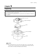
Chapter 1 Chapter Unpacking 1 Unpacking First open the carton and take out the top foam damper, then lift the printer main body out of the carton, holding the bottom of the printer firmly. Also keep the carton and packing materials as the printer must be packed with those materials for future shipment. Printer accessories Upper foam damper Printer Lower foam damper Carton CAUTION · When taking the printer out of the carton, prepare ample space to set the printer down.
Chapter 1 Unpacking 1.1 Printer accessories First, you should check that all of the following accessories are put in the carton. If any are missing, please contact your supplier.
Chapter 2 Chapter Safety Precautions 2 Safety Precautions This chapter describes safety precautions when using the printer. Please read and understand the precautions in this chapter before using the printer. l Safety signs The various safety signs included in this manual and pasted on the printer are intended to inform you of the correct and safe handling of this printer and protect against personal injury and property damage.
Chapter 2 Safety Precautions Avoid unsafe places Avoid unsafe places such as the top of a shaky desk, an uneven surface or any area subject to vibration. Failure to observe this precaution may cause the printer to fall or turn over, resulting in injury. Dot not put water-filled containers nearby Do not put containers filled with water or chemical liquids such as vases and cups near the printer.
Chapter 2 Safety Precautions Power cord Do not damage, break or modify the power cord. Putting heavy objects on the power cord or heating or pulling it may cause damages, leading to fire and electrical shock. If the power cord is damaged (e.g., the core is exposed or the wire broken), contact our service personnel. Continued use without corrective action may result in fire or electrical shock. When using, do not bend, twist, or pull the power cord.
Chapter 2 Safety Precautions CAUTION Avoid high-humidity areas Do not put the printer in areas with high-humidity or heavy condensation. If moisture has condensed on the printer, turn off the power switch immediately and leave the printer for a while until the moisture dries up. Using the printer when damp may result in electrical shock. Carrying Before carrying the printer, be sure to remove the plug from the outlet and the connecting cable to the outer equipment.
Chapter 2 Safety Precautions Opening/closing the top cover When opening/closing the top cover, be careful not to catch your fingers between the cover and chassis. Printhead The printhead remains at a high temperature immediately after printing. Therefore, be careful to avoid contact with the printhead when replacing the ribbon or media or cleaning the printer immediately after printing. Failure to observe this precaution may result in burning.
Chapter 2 Safety Precautions l Installation precautions After reading and understanding the safety signs, install the printer, observing the following precautions: Avoid dust Dust can stop the printer from cleanly printing a document. It can also cause breakdowns and shorten the printer life.
Chapter 3 Chapter Names and Functions of Printer Parts 3 Names and Functions of Printer Parts This chapter describes the names and functions of each part of the printer. 3.1 Printer main body 1. Top cover The top cover is an upper part of the whole cabinet of the printer. To open it, catch holds (embossed patterns on the surface) on both sides of the top cover with your fingers and open it all the way until it stops at hinges. To close it, just return slowly to the original position.
Chapter 3 Names and Functions of Printer Parts 2.
Chapter 3 Names and Functions of Printer Parts 3.
Chapter 3 Names and Functions of Printer Parts 3.2 Control panel The control panel consists of an LCD displaying two lines of eight characters, two LEDs and six control keys. Two functions are assigned to each key except the MODE key. = Indications LCD (Display) Shows the current printer status by a message on the display. POWER LED Lights up when the printer power is turned on. READY LED · Lights up when the printer is placed into the print ready state.
Chapter 3 Names and Functions of Printer Parts = Control keys On the control panel legend, in Ready mode, the text written ABOVE each key shows the key’s function. In Menu mode, the text written BELOW each key shows the key’s function. MODE key When the MODE key is pressed, the printer is placed into the Ready mode. When the MODE key is pressed again, the printer is placed into the Menu mode. Each time the MODE key is pressed, the printer toggles between the Ready mode and Menu mode.
Chapter 3 Names and Functions of Printer Parts MODE key Printer enters the Menu mode, and the ‘* Page Setup’ menu is shown on the LCD (Display). < Key functions in the Menu mode MENU key Selects the next Group Menu or Menu Item. (See P35-37) UP key · Selects the next Group Menu or Menu Item. (See P35-37) · Selects the next Value of the Menu Item. (See P35-37) DOWN key · Selects the previous Group Menu or Menu Item. (See P35-37) · Selects the previous Value of the Menu Item.
Chapter 4 Chapter Media (Paper) and Ribbon 4 Media (Paper) and Ribbon This chapter describes all of the types of media available for this printer and how to load the media and ribbon. Unless otherwise specified, the term ‘media,’ ‘paper,’ ‘page,’ ‘labels,’ or ‘tags’ is referring to any media that is being printed using the printer. 4.1 Types of media We recommend that you should use a genuine Citizen media (paper) or its equivalent.
Chapter 4 Media (Paper) and Ribbon ¨ Center-punched hole tag Holes (2.5mm diameter) are perforated lengthwise along the central line of the tag. ¨ Black mark tag Black marks are printed on the back of the tag at the center or on the right side in the direction of feed. ¨ Corner-with-a-radius cut tag The cuts on the edge of this tag are deeper than the cuts on center-hole tag.
Chapter 4 Media (Paper) and Ribbon = Label Media with adhesive material on the back are referred to as labels. Labels are peeled off the liner piece by piece and stuck to a product or item. ¨ Labels with inter-label gap There are gaps between labels. ¨ Black mark label Black marks are printed on the back of the label line on the central line or right side in the direction of feed.
Chapter 4 Media (Paper) and Ribbon 4.2 Media size Minimum value mm (in) Maximum value mm (in) A Label width 76.2 (3) 228.6 (9) B Liner width 76.2 (3) 228.6 (9) C Label left edge position 0 D Gap between labels 2.54 (0.10) 2 (0.079) 508 (20) E Label length 12.7 (0.5)* 508 (20) F Label pitch 12.7 (0.5) 508 (20) G Liner thickness 0.06 (0.0024) 0.089 (0.0035) H Paper total thickness 0.14 (0.0055) 0.254 (0.01) I Notch right end position 3.75 (0.148) J Notch length 3.75 (0.
Chapter 4 Media (Paper) and Ribbon 4.3 Loading media (paper) This printer is designed to align the center of the media (paper) with the center of the printhead, regardless of media (paper) width. Refer to the scale on the paper guide plate (see P30) for aligning media (paper) or ribbon. And for reference, the center of the gear of the paper guide drive mechanism, which is located on the bottom of the printer main body, is the center of the media (paper).
Chapter 4 Media (Paper) and Ribbon (3) Make the maximum media loading space by moving both-side paper guides fully to their end. Printhead assembly Transparent sensor guide Paper guide (on both sides) Transparent sensor guide release lever Printhead release lever 4 Install the inward-wound roll media as follows: (1) Place the paper holder shaft onto the round cuts on the paper guides and paper holder shaft supporting plates.
Chapter 4 5 Route the roll media over the platen out to the front of the printer. Path of inward-wound roll media 6 Media (Paper) and Ribbon Path of outward-wound roll media First lower the transparent sensor guide fully to the end and push it to lock, then lower the printhead assembly fully to the end and push it to lock. Printhead assembly Transparent sensor guide Note: For media sensor adjustments, see P29. For loading ribbon, see P23.
Chapter 4 Media (Paper) and Ribbon 7 The roll media is now loaded. Lastly close the top cover. Fanfold media 1 Remove ribbon holder disks (two) from the ribbon holder assembly. Place the paper holder shaft onto the round cuts on the paper guides and paper holder shaft supporting plates on both sides.
Chapter 4 Media (Paper) and Ribbon 4.4 Loading ribbon We recommend that you should use a genuine Citizen ribbon or its equivalent. This printer is designed to align the center of the media (paper) with the center of the printhead, regardless of media width. Refer to the scale on the tear bar for aligning media (paper) or ribbon on page. And for reference, the center of the gear of the paper guide drive mechanism, which is located on the bottom of the printer main body, is the center of the media.
Chapter 4 Media (Paper) and Ribbon 2 Two ribbon bobbins are used for loading ribbon; one is inserted in the source (unused) ribbon core and the other is inserted in the destination ribbon core. And wind ribbons two or three times around the destination ribbon core by hand. NOTE The following procedure may help you load the ribbon more easily.
Chapter 4 3 Media (Paper) and Ribbon Perform the following sequence; open the top cover all the way until it stops at hinges, and unlock the printhead assembly by pushing the printhead release lever and raise it until it stops and stands upright. Printhead assembly Printhead release lever 4 Hold by both hands the ribbon with a length of about 300 mm (1 ft) unwound between bobbins; the left hand grips the source ribbon and the right hand grips the destination ribbon.
Chapter 4 Media (Paper) and Ribbon 5 Temporarily winding the ribbon with a length of about 300 mm (1 ft) unwound between bobbins around the lower, bottom side of the printhead assembly, first fit both sockets of the destination and source ribbon bobbins, then click into place both knobs of the destination and source ribbon bobbins.
Chapter 4 Media (Paper) and Ribbon Ribbon tension adjustments The ribbon tension should be adjusted as needed according to the media (paper) width to prevent ribbon from slackening or wrinkling. To increase tension torque, turn the source ribbon bobbin (the deeper side viewed from the front of the printer) knob clockwise until the required number is obtained from the scale, while stopping the gear with a coin inserted in the slit on the ribbon bobbin support and held down.
Chapter 4 Media (Paper) and Ribbon 4.5 Printhead adjustments The printhead adjustments should be made according to the type of media (paper), using a printhead adjustment lever located on the back of the printhead assembly.
Chapter 4 Media (Paper) and Ribbon 4.6 Media sensor adjustments Laterally adjustable upper and lower media sensors are equipped; the upper media sensor, i.e. the transparent sensor (light-receiving device) detects the presence of gaps between labels, center-punched holes or corner-with-a-radius cuts on the tags, and the lower media sensors, i.e.
Chapter 4 Media (Paper) and Ribbon 3 When the media being used is a center-punched hole or corner-with-a-radius cut tag, first align the T mark (in proximity to two light-emitting devices) with the holes or cuts on the tag (at this time, read the scale), then lower the transparent sensor guide fully to the end and push it to lock and move the transparent sensor to the scale same as read before. Transparent sensor (light-receiving device) 4 The media sensor adjustments are now completed.
Chapter 4 Media (Paper) and Ribbon 4.7 Ribbon guide plate adjustments The ribbon guide plate may need adjusting to remove wrinkles on the ribbon. Adjust ribbon guide plate as follows: 1 Open the top cover all the way until it stops at hinges and unlock the printhead assembly by pushing the printhead release lever and open it towards the left side of the printer all the way until it stops and stands upright. 2 Detach the ribbon bobbins form the ribbon bobbin holders.
Chapter 4 Media (Paper) and Ribbon - 32 -
Chapter 5 Chapter Power ON and Using the Control Panel 5 Power ON and Using the Control Panel After loading the media and ribbon, connect the power cord and turn your printer on. 5.1 Connecting to a power outlet First plug the power cord into the AC power input on the back of the printer, then plug the other end of the power cord into the AC power outlet. CAUTION The specifications of the power cord may vary, depending on the rules of the destination.
Chapter 5 Power ON and Using the Control Panel 5.2 Turning the printer ON Turn ON the power switch. · Press “|” for ON. · Press “O” to turn off the printer. Once the power is turned ON, the following initial messages are displayed on the screen for about three seconds. Power ON Firmware version is displayed CF000100 DD/MM/YY System Starting The printer tests the printhead for damage Checking Head Failed XXX.
Chapter 5 Power ON and Using the Control Panel 5.3 Ready Mode and Menu Mode This section describes the operation flow of the Ready mode and Menu mode. This printer can be easily operated using the six keys on the control panel. Ready mode READY Receive data from host computer. READY ****** STOP REPEAT FEED PAUSE Perform function: · Stop printing · Repeat last label · Feed to TOF · Pause printing Return to ready mode after 5 sec of no more data. ****** = ‘Parallel’, ‘RS232C’, etc.
Chapter 5 Power ON and Using the Control Panel Ready mode The printer is in Ready mode after power is switched on and the self-test is performed. READY The LCD (Display) shows “READY” and the READY LED is lit. In this state, you can perform the media feed, printing stop/restart etc using the keys on the control panel.
Chapter 5 Power ON and Using the Control Panel 5.5 Changing Menu Values With a Menu Item displayed on the LCD (such as Print Speed, Darkness or Baud Rate), pressing the key allows you to adjust or select the Value of the Menu Item. The and keys are used to increase or decrease a Value, such as the print speed or printing position.
Chapter 5 Power ON and Using the Control Panel Select the Print Darkness Menu Item. · Press to bring up the Print Darkness function. Print Darkness Show the Print Darkness current value. · Press to bring up the current Print Darkness value. Darkness 10 Change the setting to ²15² · Press and hold · Press to increase the Value from ²10² to ²15² Darkness 15 to save the new value and printer returns to the Menu Item. When is pressed, the display goes back to ‘* Page Setup.
Chapter 5 Power ON and Using the Control Panel 5.7 Producing a Test or Configuration Print When the Test Mode is selected from the Group Menu, test and configuration prints, head element check and Hex Dump mode can be selected. The two test print patterns and two configuration printouts are available. = Example: producing a test pattern print Press the key to display the Group Menu display.
Chapter 5 Power ON and Using the Control Panel 5.8 Turning the printer OFF Do not turn the printer OFF suddenly. If the printer is printing, press the or key and wait for the printer to stop printing before turning the power switch OFF.
Chapter 6 Chapter Configuring Your Printer Using the Menus 6 Configuring Your Printer Using the Menus This chapter explains all the possible menu options for configuring the barcode printer. Refer to Chapter 5 for information on the operation of the menus system and which keys perform which actions. 6.1 The Group Menu The printer has two modes of operation: Ready mode and Menu mode. To switch between the modes, press the key.
Chapter 6 Configuring Your Printer Using the Menus 6.2 Page Setup Menu The Page Setup Menu allows the setting of items such as print speed, print darkness, direct or thermal transfer printing and horizontal and vertical position adjustments. Key * Page Setup Range Toggle Inch mode Label Width Width 3.00IN Width 8.53IN Width 8.64IN Width 76.2mm Width 216.7mm Width 219.
Chapter 6 Configuring Your Printer Using the Menus Inch mode Horizont Shift Shift - 1.00IN Shift 0.10IN Shift 1.00IN Shift 2.5mm Shift 25.4m Metric mode Shift - 25.4mm 6.3 System Setup Menu The System Setup Menu provides access to configure the hardware settings within the printer such as the type of media sensor used and the threshold for gap detection, metric or imperial (inches) selection, print resolution and time and date setting, if a clock module is installed.
Chapter 6 Configuring Your Printer Using the Menus Inch mode Metric mode Print Res.DPI DPI 300/150 DPI 300/150 AutoCal Mode Cal. Yes/No Cal. Yes/No DPmm DPmm 12/6 SELECT Cal. Practice Inch mode 12/6 Cal. End Metric mode MaxMedia Length Length 1.00IN Length 10.
Chapter 6 Configuring Your Printer Using the Menus 6.4 After Print Menu The After Print Menu allows you to configure what the printer does once the label has been printed, including whether the printer feeds to the tear position after a batch of labels, whether the printer cuts the labels. * After Print Key Range Tear Mode Tear On/Off Tear On/Off Note: Menu Item on LCD with bold line is default. When Tear Mode is Off Inch mode Paper Position Position 0.00IN Position 2.
Chapter 6 Configuring Your Printer Using the Menus 6.5 Interface Setup Menu The Interface Setup Menu configures the baud rate, parity, data length, protocols and stop bits for the standard serial interface. It also allows for the configuration of the optional network interface, including IP address, subnet mask and gateway addresses.
Chapter 6 Configuring Your Printer Using the Menus 6.6 Permanently Saving Settings Menu Settings made within the menu system of the printer are saved in standard memory. When the printer is switched off, these settings will be lost unless they are save to the non-volatile memory inside the printer. The Permanently Saving Settings Menu has just one option.
Chapter 6 Configuring Your Printer Using the Menus 6.8 Menu Mode Description Group Menu * Page Setup Menu Item Label Width Print Speed Print Darkness Default Value 8.53in 216.7mm 04 IPS 10 Range of Values 3.00 - 8.64in 76.2 - 219.5mm 02 - 04 IPS 00 - 30* Print Method TT Ribbon Torque 3 DT / Direct Thermal TT / Thermal Transfer 1-5 Continu. MediaLen 10.00in 254.0mm 0.00in 0.00mm 10.00in 254.0mm See Thru Vertical Position Horizont Shift * System Setup Media Sensor Sensor Monitor 0.25 - 40.
Chapter 6 Group Menu Menu Item * System Setup Time Setting Date Setting Settings Lock Configuring Your Printer Using the Menus Default Value Range of Values ¾ ¾ ¾ ¾ Off On Off Description Set time (hours and minutes). Set date (day, month and year). When it is On, set values with keys are locked and set values with command are ignored. Keyboard Lock Off On Off Lock keyboard.
Chapter 6 Configuring Your Printer Using the Menus Group Menu * Interface Menu Item RS-232C Baud Default Value 115200 RS-232C Parity None RS-232C Length 8 bits RS-232C Stop bit 1 bit RS-232C X-ON Yes Network Address 192.168. 254.254 000.000. 000.000 000.000. 000.000 Subnet Mask Gateway Address Range of Values 115200 600 1200 2400 4800 9600 14400 19200 38400 57600 None Odd Even 8 bits 7 bits 1 bit 2 bits No Yes 000.000.000.000 255.255.255.255 000.000.000.000 255.255.255.255 000.000.000.
Chapter 7 Chapter Troubleshooting 7 Troubleshooting When an error occurs, an error message is displayed on the LCD panel. This chapter describes corrective actions to be taken when error message is received or problems or difficulties are experienced. 7.1 Items to check in case of trouble If problems or difficulties are experienced during the operation of the printer, please check the following table to try and resolve your problem. Symptom The LCD stays blank when the printer power is turned ON.
Chapter 7 Troubleshooting Symptom Text is not printed cleanly. Check Remedy 1. Is the paper and ribbon loaded properly? 2. Is the print density too dark or faint? Print position changes. Ribbon wrinkles. 1. Load the paper and ribbon properly. 2. Set the proper print density via the menu or control software. 3. Is the platen dirty or deformed? 3. If the platen is dirty, remove the dirt using ethyl alcohol. If the platen is deformed, contact our service personnel for replacement. 4.
Chapter 7 Troubleshooting 7.2 Error messages and corrective actions The printer will be placed in error status and an error message will be displayed on the LCD (Display) if the printer has not been prepared properly for printing or printer setup conditions are not correct. Check error messages and take corrective actions to clear error. If a message other than the following is displayed, please contact our service personnel.
Chapter 7 Troubleshooting - 54 -
Chapter 8 Chapter Maintenance 8 Maintenance Since this printer uses a thermal head and a carbon ink ribbon、thermal paper dust etc may adhere to the printhead or other related parts. In this case, printing errors or failure of the printhead may occur. If paper dust or ribbon material adheres to the printhead, irregular printer movements, paper jams or poor print quality may occur. Therefore, be sure to clean the printhead, platen and paper path periodically.
Chapter 8 Maintenance 8.2 Cleaning method Remove dirt, paper dust, adhesive materials for labels etc upon completion of printing.
Chapter 8 Chapter Maintenance 9 Specifications 9.1 General specifications Item CLP-8301 Printing method Thermal Transfer/Direct Thermal Printhead resolution 300 DPI (11.81 dots/mm) approx Maximum print width 219.5 mm (8.64”) Print length 12.7 mm (0.5”) - 508.0 mm (20”) Print speed 2 - 4 IPS Media Max. roll media outer diameter: 203 mm (8 in) Max. media width: 228.6 mm (9”) Media pitch detections Movable transparent and reflective sensors Ribbon Max.
Chapter 9 Specifications 9.2 Interfaces 1 Serial interface Specifications Transfer method: Start stop synchronous dual communication system Signal level: RS-232C Baud rate: 2400, 4800, 9600, 14400, 19200, 38400, 57600, 115200 bps Data bits: 7 or 8 Start bits: 1 Stop bits: 1 or 2 Parity: Even, odd, or none Connector: D-SUB 25PIN 17LE-13250-27(D41)(DDK) or its equivalent XON/XOFF protocol XON code output requirements: · Communication is enabled after power is turned ON.
Chapter 8 Maintenance DTR protocol DTR signal “Ready (High)” level requirements: The following must be satisfied: · Printer is on line. · Receive buffer has more than 128 bytes available. Note: When receive buffer has less than 128 bytes available, DTR signal becomes “Busy (Low)” level and this “Busy (Low) level is kept until receive buffer has at least 1K bytes available. DTR signal “Busy (Low)” level requirements: The following must be satisfied: · Printer is in error.
Chapter 9 Specifications 2 Parallel interface Specifications Transfer method: 8-bit parallel (compatibility mode) Synchronous: Strobe pulse Handshaking: ACKNLG and BUSY signals Signal level: TTL Printer side: 36-pin non-phenol type Pin assignment Pin No.
Chapter 8 Maintenance Timing chart Min 750ns STROBE Max 500ns BUSY 2.5ms(typ.) ACKNL Min 750ns Min 750ns DATA ACKNLG “Low” shows that the printer requests the computer to send data. BUSY “High” shows that the printer cannot receive data and BUSY “Low” shows that the printer now can receive data from the computer.
Chapter 9 Specifications 9.3 Printable area 6.35mm (0.07”) 6.35mm (0.07”) 215.9mm (8.5”) 107.95mm (4.25”) Printable area 2592 Dots 1 Dot 228.6mm (8.
Chapter 8 Maintenance Movable sensors Maximum left edge of media 228.6mm (8.64”) (maximum media 114.3mm (4.32”) Center of media and printhead 140mm (5.5”) (sensor movable range) Media Sensor Detection Mark A/D Voltage Setup Guide Setup Voltage Voltage Level Variable Voltage Black Mark Reflective Center Low No Mark area 2.1V 1.7V or less 1.2V 2.2V Edge High No Mark area 1.05V 1.5V or more 1.0V 2.0V Edge High Mark area (no media) 2.5V 1.5V or more 1.0V 2.
Chapter 9 Specifications 9.5 Environmental requirements 1 Printer operating conditions for ensuring print quality Operating temperature: 5°C - 40°C Humidity: 25% - 85% RH (non-condensing) Humidity % 85 50 25 0 5 35 40 Temperature °C 2 Printer storage conditions Storage temperature: -20°C - 60°C Humidity: 25% - 85% RH (non-condensing) (Printer should be stored in a condition that the printhead is up and no media and ribbon are loaded.
Chapter 8 - 65 - Maintenance
Citizen Systems Europe GmbH Mettinger Strasse 11 337 Bath Road, Slough 73728 Esslingen Berkshire, SL1 5PR Germany United Kingdom www.citizen-europe.