CITIZEN User’s Manual MINI DOT MATRIX PRINTER MODEL iDP-3530 Japan CBM Corporation Information Systems Div.
iDP-3530 User’s Manual IMPORTANT: This equipment generates, uses, and can radiate radio frequency energy and if not installed and used in accordance with the instruction manual, may cause interference to radio communications. It has been tested and found to comply with the limits for a Class A computing device pursuant to Subpart J of Part 15 of FCC Rules, which are designed to provide reasonable protection against such interference when operated in a commercial environment.
iDP-3530 User’s Manual CONTENTS 1. Introduction ............................................................................................................................................................4 1-1 Features ............................................................................................................................................................4 1-2 Accessories........................................................................................................................
iDP-3530 User’s Manual 1. Introduction The iDP 3530 is a dot impact printer which can be utilized for a wide range of applications including, data communications terminals, P.O.S. terminals and kitchen printers. High speed performance is made possible by a bi-directional printing system. Since this printer is compact, lightweight and equipped with an abundance of functions, it can be easily employed for a variety of different tasks.
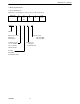
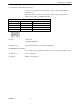
iDP-3530 User’s Manual 2. Basic Specifications 2-1 Type classifications Printer types are classified according to the system shown below.
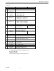
iDP-3530 User’s Manual 2-2 Features 1 2 3 Item Print Method Character composition Character number per line 4 Print speed 5 Character size 6 7 Line pitch Paper size 8 Interface 9 Paper end detector iDP3530F iDP3530P Bidirectional serial dot impact method. 7 x 7 dots (Incl. Half dot). 23 columns: 230dot / line. 28 columns: 280dot / line. 40 columns: 360dot / line. 23 columns: approx. 4.0 line / sec. 28 columns: approx. 3.5 line / sec. 40 columns: approx. 3.0 line / sec. 23 columns: 1.8(W) x 2.
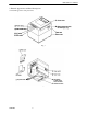
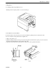
iDP-3530 User’s Manual 3. External Appearance and Parts Descriptions 3-1 External appearance and parts names Fig. 1 Fig.
iDP-3530 User’s Manual 3-2 Parts Descriptions (1) Power Cord Insert the plug end into an electric outlet. (2) Power Switch Power is supplied to the printer by turning this switch on. (3) Power Lamp This lights up when the power switch is “ON” and goes out when turning “OFF”. (4) SEL / ALARM Lamp This lights up when the printers is in SELECT state ( ON-LINE) and goes out when in DESELECT state (OFF-LINE). The printer can print out the data only when this lamp is on.
iDP-3530 User’s Manual (8) Cash Drawer or Paper Winder Connector To be used to control the P.O.S. cash drawer or paper winder by DIP SWITCH setting (Ref.7-1). When this connector is used for each drawer solenoid voltage 24V, register over 36Ω, for paper winder, use CBM model AW-3. Pin No 1 2 3 4 Connector Pin Assignment Signal Name Function Vp DC24V, 0.8A or less VL Solenoid FG GND FG GND Connector : Printer side : 5045-04A (MOLEX) (9) Printer Cover Open when replacing the cassette ribbon and Paper.
iDP-3530 User’s Manual 4. Preparation 4-1 Attaching / Removing the Printer Cover Attaching and removing the printer cover as shown in Fig. 3. Fig.3 4-2 The Ribbon Cassette Installation To insert the ribbon, disconnect the power source beforehand. If printing has been continued for many hours, be careful not touch printer head as it might be hot.
iDP-3530 User’s Manual 4-3 Loading and Changing the Paper Using Paper Roll 1) Cut the paper in right angle to its longitudinal center line as shown in Fig. 7. 2) Insert the paper into insertion inlet on the rear side of printer. 3) Turn on the power switch and feed the paper by pushing the LF switch. 4) When the printing paper comes out of the clearance (paper cutter part) on the printer cover, fix the paper by means of paper holder, then set in on the main unit. Fig.
iDP-3530 User’s Manual 4-4 Attaching / Removing the Paper Cover and Stacker 1) Attaching and removing the paper cover and the stacker as shown in Fig. 9, 10. 2) Capacity of stacker The maximum size of fun-fold paper sheaf which can be stored in this stacker is 3 to 3.5 (W) x 6 (H) x 1.6 (D) inches. Fig. 9 Fig. 10 4-5 Self Test Printing Your printer has a built in self print function for purpose of checking print operation without the need for any other external device.
iDP-3530 User’s Manual 4-6 Alarm and Paper Near-End Detection This printer has the paper near-end sensor to stop the operation when the paper comes to near-end, sending out both BUSY and FAULT signals. This status is indicated by the SEL / ALARM lamp blinking at-an interval of 1.0 second. If the printer goes alarm, the printer stops printing out and outputs FAULT signal – OFF-LINE state. This status makes the SEL / ALARM lamp blink at an interval of 1/4 second.
iDP-3530 User’s Manual 5. Serial Interface 5-1 Specifications 1) Synchronism : Asynchronous 2) Baud rate : 1200, 2400, 4800, 9600 BPS (Selected by user) 3) Composition of one word : Start bit : 1 bit Data bit : 7 or 8 bit (selected by user) Parity bit : Odd, even or parity (selected by user) Stop bit : 1 bit or more.
iDP-3530 User’s Manual 5-3 Input / output Signals RS-232C Circuit Input (RD) [Printer side] [Host side] uPD4711 or equivalent Output (DTR,FAULT) [Printer side] [Host side] uPD4711 or equivalent DTR : (-8V) BUSY : (+8V) READY FAULT : (-8V) Normal : (+8V) Abnormal CITIZEN 15
iDP-3530 User’s Manual 5-4 Data Composition [1] Start bit [2] Data bits (and parity bit) [3] Stop bit (1 bit more) 1) Start bit 1/2 bit past the line dropping from MARK to SPACE, a status reading is taken again. If the reading is SPACE, a start bit is recognized. 2) Data bits and Parity bit Data bit and Parity bit are checked out every bit form the half point of start bit. Signal level of these points (Mark = 1, Space = 0) are read as input data.
iDP-3530 User’s Manual 6. Parallel Interface 6-1 Specifications 1) Data Input System : 8 bit parallel (Data 1-8) 2) Control Signal 3) Compatible Connector : ACK, BUSY, STB, FAULT : Printer side. To equivalent AMPHENOL 57-40360 : Cable side. To equivalent AMPHENOL 57-30360 6-2 Connector Pin Assignment Pin No. 1 2 3 4 5 6 7 8 9 10 11 12 13 14 15 16 17 18 CITIZEN Signal Name STB Data 1 Data 2 Data 3 Data 4 Data 5 Data 6 Data 7 Data 8 ACK BUSY GND +5V Level GND GND GND Frame GND Pin No.
iDP-3530 User’s Manual 6-3 Description of Input / Output Signals 1. Input / Output Signals Input Signals (To Printer) DATA 1 : 8 bit signal (Positive logic) DATA 2 : 8 bit signal (Positive logic) DATA 3 : 8 bit signal (Positive logic) DATA 4 : 8 bit signal (Positive logic) DATA 5 : 8 bit signal (Positive logic) DATA 6 : 8 bit signal (Positive logic) DATA 7 : 8 bit signal (Positive logic) DATA 8 : 8 bit signal (Positive logic) STB : A strobe signal for reading in 8 bit data.
iDP-3530 User’s Manual 6-4 Electrical Characteristics 1 Input Signal Level All input signals are TTL level. “HIGH” Level = 2.0V Min. “LOW” Level = 0.8V Max. 2 Output Signal Level “HIGH” Level = 2.4V Min. “LOW” Level = 0.4V Max. 3 Input / Output Conditions All of the input signals are pulled up by 3.3K ohms.
iDP-3530 User’s Manual 6-5 Timing Chart Data Input and Print Timing T1 ……… 0.5µs Min. T2 ……… 0.5µs Min. T3 ……… 0.5µs Min. T4 ……… 270ns Max. T5 ……… 5.5µs Typ. T6 ……… 500ms Min.
iDP-3530 User’s Manual 7. Function Selection by Dip Switch 7-1 Dip-Switch (DS-1) Setting No. Function to chose SEL / DSEL state (when powered on) to chose CR code functions to chose Character Table to chose Character Table by the Country to chose output signal for external device - not used - not used - 1 2 3 4 5 6 7 8 No. 4 5 U.S.A.
iDP-3530 User’s Manual 7-3 Dip-Switch Location Power off and remove the printer cover before setting the Dip-Switches.
iDP-3530 User’s Manual 8. Print Control Functions 8-1 SI & SO Code Symbol SI SO Code (Hex.) 8 bit data 0F Standard character designation (Same as US) 0E Double-width character designation (Same as RS) 7 bit data Designation of SI side character Designation of SO side character 8-2 Function Code Symbol LF CR RS US FF DC 1 DC 2 DC 3 CAN ESC + "C" ESC + "0" BEL CITIZEN Code (Hex.) Function 0A Feeds a new line after printing. Feeds a new line after printing.
iDP-3530 User’s Manual 8-3 Input Data Formats The data input to the printer is made by the codes listed in the Character Code Table. (1) Standard Character Print Mode Designation. US (1F) DATA CR (0D) The printer goes automatically to the standard character mode immediately after power-on initialization or line feed. Therefore, US code can be omitted. In addition, an automatic line feed is carried out after inputting the data for one line (Full Buffer Print).
iDP-3530 User’s Manual (5) Form Feed DATA With this code, paper feed goes on. If there is data in the buffer when this code is input, the printer does from feed printing. The top of form for the next page is made in accordance with the page length which was specified with ESC + “C” + “n”. Top of position of the page is determined when power is turned on or when page length is specified with ESC + “C” + “n”. (6) Canceling CAN (18) All the data in one line prior to CAN are cleared entirely with this code.
iDP-3530 User’s Manual 9. Initial Setting Following are automatically set after Power-on. (1) Printer head returns to its start position. (2) SELECT (ON-LINE) or DESELECT (OFF-LINE) status may be chosen by the Dip Switches for Pre-Setting. (3) Print buffer is cleared. (4) Standard character mode is set. (5) 66 lines per page is set. (6) The first line set at the present line. (7) Designation of Red printing is cleared. (8) For 7 bit data, character code SI is applied. 10.
iDP-3530 User’s Manual 11.
iDP-3530 User’s Manual 11-2 Individual Country Character Codes CITIZEN 28