iDP-3535 User’s Manual CITIZEN User’s Manual MINI DOT MATRIX PRINTER MODEL iDP-3535 Japan CBM Corporation Information Systems Div.
iDP-3535 User’s Manual IMPORTANT SAFETY INSTRUCTIONS s Read all of these instructions and save them for later reference. s Follow all warnings and instructions marked on the product. s Unplug this product from the wall outlet before cleaning. Do not use liquid or aerosol cleaners. Use a damp cloth for cleaning. s Do not use this product near water. s Do not place this product on an unstable cart, stand of table. The product may fall, causing serious damage to the product.
iDP-3535 User’s Manual IMPORTANT: This equipment generates, uses, and can radiate radio frequency energy and if not installed and used in accordance with the instruction manual, may cause interference to radio communications. It has been tested and found to comply with the limits for a Class A computing device pursuant to Subpart J of Part 15 of FCC Rules, which are designed to provide reasonable protection against such interference when operated in a commercial environment.
iDP-3535 User’s Manual CONTENTS 1. Introduction ............................................................................................................................................................5 1-1 Features ............................................................................................................................................................5 1-2 Accessories.......................................................................................................................
iDP-3535 User’s Manual 1. Introduction The iDP 3535 is a dot impact printer which can be utilized for a wide range of applications, such data communications terminals, P.O.S. terminals and kitchen printers. High speed performance is made possible by a bi-directional printing system and, since this printer is compact, lightweight and equipped with an abundance of functions, it can be easily employed for a variety of different tasks.
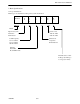
iDP-3535 User’s Manual 2. Basic Specifications 2-1 Type classifications Printer types are classified according to the system shown below.
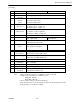
iDP-3535 User’s Manual 2-2 Features 1 2 3 Item Print Method Character composition Character number per line 4 Print speed 5 Character size 6 7 Line pitch Paper size 8 Interface 9 Paper end detector 10 11 12 13 14 15 16 17 Ribbon cassette Paper winder and Cash drawer Power voltage Power Consump. Operation temp. & humidity Storage temp. Net weight External dimensions Notes: CITIZEN iDP3535F Bidirectional serial dot impact method. 7 x 7 dots (Incl. Half dot). 23 columns: 230dot / line.
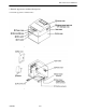
iDP-3535 User’s Manual 3. External Appearance and Parts Descriptions 3-1 External Appearance and Parts names Fig.1 Fig.
iDP-3535 User’s Manual 3-2 Parts Descriptions (1) Power Cord Insert the plug end into an electric outlet. The socket-outlet should be installed near the equipment and should be easily accessible. (2) Power Switch Power is supplied to the printer by turning this switch on. (3) Power Lamp This lights up when the power switch is “ON” and goes out when turning “OFF”. (4) SEL / ALARM Lamp This lights up when the printers is in SELECT state ( ON-LINE) and goes out when in DESELECT state (OFF-LINE).
iDP-3535 User’s Manual (9) Printer Cover Open when replacing the cassette ribbon and paper. (10) Manual Paper Feed Knob Use to adjust the paper position (available only on pin tractor paper feeding model). (11) Rear Cover Cover for roll paper. (12) Stacker Basket for fan-fold paper. (13) Cash Drawer Connector This connector is used to drive cash drawers. (Ref.
iDP-3535 User’s Manual 4. Preparation 4-1 Inserting / Removing the Printer Cover Inserting and removing the printer cover as shown in Fig. 3. Fig.
iDP-3535 User’s Manual 4-2 The Ribbon Cassette Installation To insert a ribbon, disconnect the power source beforehand. When the printer has been printing for many hours, be careful not touch printer head as it might be hot. 1) Remove the printer cover 2) While inserting the ribbon into the space between the print head and the ribbon guide, press the cassette into the holder unit until it clicks into place. (Ref. To Fig.
iDP-3535 User’s Manual 4-3 Loading and Changing the Paper Using Paper Roll 1) Cut the paper in right angle to its longitudinal center line as shown in Fig. 7. 2) Insert the paper into insertion inlet on the rear side of printer. 3) Turn on the power switch and feed the paper by pushing the LF switch. 4) When the printing paper comes out of the clearance (paper cutter part) on the printer cover, fix the paper by means of paper holder, then set in on the main unit.
iDP-3535 User’s Manual Using Fan-fold Paper 1) Remove the printer cover. 2) Set the imprint face of the paper down ward and put into the paper entrance. 3) If necessary to adjust the sprocket-wheel’s position, free the wheels using the lever on both side. Slide them to the appropriate position, and lock them back. 4) Hook some of the paper’s perforations on the sprockets and forward the paper into the printer mechanism by pulling and turning the paper-feed knob until the paper’s tip reaches the platen.
iDP-3535 User’s Manual 4-4 Inserting / Removing the Paper Cover and Stacker 1) Inserting and removing the paper cover and the stacker as shown in Fig. 9, 10. 2) Capacity of stacker The maximum size of fun-fold paper sheet which can be stored in this stacker is 3 to 3.5 (W) x 6 (H) x 1.6 (D) inches. Fig. 9 Fig. 10 4-5 Self Test Printing Your printer has a built in self print function for purpose of checking print operation without the need for any other external device.
iDP-3535 User’s Manual 4-7 General Cautions 1) Never operate your printer without loading paper and ribbon cassette. Any printing without paper and ribbon cassette may cause damage to printer head. 2) Replace ribbon cassette before it is worn with rents. 3) Be careful not to drop any foreign matters, such as paper clips, pins and the like into your printer. These can cause mechanical trouble. 4) Nothing shall be placed on the ventilation vents of the printer.
iDP-3535 User’s Manual 5. Serial Interface 5-1 Specifications 1) Synchronism 2) Baud rate : Asynchronous : 1200, 2400, 4800, 9600 BPS (Selected by user) : Start bit : 1 bit : Data bit : 7 or 8 bit (selected by user) : Parity bit : Odd, even or parity (selected by user) : Stop bit : 1 bit or more.
iDP-3535 User’s Manual 5-3 Input / output Signals RS-232C Circuit Input (RD) [Printer side] [Host side] MAX232 or equivalent Output (DTR,FAULT) [Printer side] [Host side] MAX232 or equivalent DTR : (-8V) BUSY : (+8V) READY FAULT : (-8V) Normal : (+8V) Abnormal CITIZEN 18/38
iDP-3535 User’s Manual 5-4 Data Composition 1 2 3 Start bit Data bits (and parity bit) Stop bit (1 bit more) 1) Start bit 1/2 bit past the line dropping from MARK to SPACE, a status reading is taken again. If the reading is SPACE, a start bit is recognized. 2) Data bits and Parity bit Data bit and Parity bit are checked out every bit form the half point of start bit. Signal level of these points (Mark = 1, Space = 0) are read as input data.
iDP-3535 User’s Manual 5-5 Error Detection The printer detects Parity, Framing and Overrun Error. When any error is detected, the data is printed out as (7FH). Framing Error; Framing error occurs when SPACE signal is checked out at STOP BIT and the printer print out (7FH). Parity Error; Parity check is carried out only when user designates it on the printer pre-setting. Input Control and Buffering; (over-run-error) The printer is designed to output DTR signals for each word.
iDP-3535 User’s Manual 6. Parallel Interface 6-1 Specifications 1) Data Input System 2) Control Signal 3) Compatible Connector : 8 bit parallel (Data 1-8) : ACK, BUSY, STB, FAULT, RESET(OPTION) : Printer side, Equivalent to AMPHENOL 57-40360 : Cable side. Equivalent to AMPHENOL 57-30360 6-2 Connector Pin Assignment Pin No. 1 2 3 4 5 6 7 8 9 10 11 12 13 14 15 16 17 18 CITIZEN Signal Name STB Data 1 Data 2 Data 3 Data 4 Data 5 Data 6 Data 7 Data 8 ACK BUSY GND +5V Level GND GND GND Frame GND Pin No.
iDP-3535 User’s Manual 6-3 Description of Input / Output Signals 1. Input / Output Signals Input Signals (To Printer) DATA 1 : 8 bit signal (Positive logic) DATA 2 : 8 bit signal (Positive logic) DATA 3 : 8 bit signal (Positive logic) DATA 4 : 8 bit signal (Positive logic) DATA 5 : 8 bit signal (Positive logic) DATA 6 : 8 bit signal (Positive logic) DATA 7 : 8 bit signal (Positive logic) DATA 8 : 8 bit signal (Positive logic) STB : A strobe signal for reading in 8 bit data.
iDP-3535 User’s Manual 6-4 Electrical Characteristics 1 Input Signal Level All input signals are TTL level. “HIGH” Level = 2.0V Min. “LOW” Level = 0.8V Max. 2 Output Signal Level “HIGH” Level = 2.4V Min. “LOW” Level = 0.4V Max. 3 Input / Output Conditions All of the input signals are pulled up by 3.3K ohms.
iDP-3535 User’s Manual 6-5 Timing Chart Data Input and Print Timing T1 ……… 0.5 µs Min. T2 ……… 0.5 µs Min. T3 ……… 0.5 µs Min. T4 ……… 270ns Max. T5 ……… 5.5 µs Typ. T6 ……… 500ms Min.
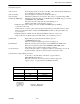
iDP-3535 User’s Manual 7. Dip-Switch Setting 7-1 Dip-Switch (DS-1) Setting No. Function 7 8 to chose SEL / DSEL State (when powered on) to chose CR code functions to chose Character Table to chose Character Table by the Country to chose output signal for external device - not used - not used - No. 4 5 U.S.A.
iDP-3535 User’s Manual 7-2 Dip-Switch (DS-2) Setting (only for Serial Interface) No. Functions 1 2 3 4 5 6 to chose Word's Length Parity Checking Parity Checking Baud rate Setting On-Line Mode *1 7 8 - not used - not used - ON OFF Factory Setting 7 bit 8 bit No Yes Even Odd - see the table below DC3 LF code DC3 DESELECT code OFF ON OFF OFF ON OFF OFF OFF Baud rate Selection No.
iDP-3535 User’s Manual 7-3 Dip-Switch Location Power off and remove the printer cover before setting the Dip-Switches.
iDP-3535 User’s Manual 7-4 Usage of the connectors (for cash drawers and paper winder) L1: external device 1 L2: external device 2 CN3 : connector for cash drawer and paper winder. PIN 1 2 3 4 SIGNAL Vp DR 1 FG FG FUNCTIONS DC24V, 0.8A Max External device 1 Frame GND connector Printer side : 5045-04A (molex) Cable side : 5209-04 (molex) CN6 : connector for cash drawers.
iDP-3535 User’s Manual Usage of the DIP switch Type Preset JP. Line JP 1 JP 2 E type ON OFF JP 3 ON Dig SW. DIP 1-6 ON OFF U-type ON ON OFF ON Paper Winder L1(AW-3) L1(AW-3) Cash Drawer L2 L1 L2 - - L2 L1 OFF - L2 Connector (PIN) CN 3-2 CN 6-2.5 CN 3-2 CN 6-2.5 CN 3-2*1 CN 6-2 CN 6-5 CN 3-2*1 CN 6-2 CN 6-5 Command Code (HEX) LF (0A) SUB (1A) BELL (07) SUB (1A) LF (0A) SUB (1A) BELL (07) SUB (1A) *1.
iDP-3535 User’s Manual For U-type only (USA type) Your iDP3535 is equipped to drive up to 2 external device – Paper Winder and / or Cash Drawers. The 4 pin molex connector and the first driver of the modular connector (pins 2 & 3) are shared by the same driver and only one device can be connected to this driver. Acceptable combinations of configurations are: A) No external devices connected. B) One Cash Drawer connected to 4-pin molex connector. Set DIPI-6 OFF.
iDP-3535 User’s Manual 8. Print Control Functions 8-1 SI & SO Code Symbol SI Code (Hex.) 0F SO 0E 8 bit data Standard character designation (Same as US) Double-width character designation (Same as RS) 7 bit data Designation of SI side character Designation of SO side character 8-2 Function Code Symbol LF Code (Hex.) 0A CR 0D RS 1E US FF DC 1 1F 0C 11 DC 2 12 DC 3 CAN 13 18 ESC + "C" ESC + "0" BEL SUB 1B, 43 1B, 4F 7 1A CITIZEN Function Feeds a new line after printing.
iDP-3535 User’s Manual 8-3 Input Data Formats The data input to the printer is made by the codes listed in the Character Code Table. (1) Standard Character Print Mode Designation. US (1F) DATA LF (0A) The printer goes automatically to the standard character mode immediately after power-on initialization or line feed. Therefore, US code can be omitted. In addition, an automatic line feed is carried out after inputting the data for one line (Full Buffer Print).
iDP-3535 User’s Manual (5) Form Feed FF(0C) With this code, paper feed goes on. If there is data in the buffer when this code is input, the printer does from feed printing. The top of form for the next page is made in accordance with the page length which was specified with ESC + “C” + “n”. Top of position of the page is determined when power is turned on or when page length is specified with ESC + “C” + “n”. (6) Canceling CAN(12) All the data in one line prior to CAN are cleared entirely with this code.
iDP-3535 User’s Manual 9. Initial Setting Following are automatically set after Power-on. (1) Printer head returns to its start position. (2) SELECT (ON-LINE) or DESELECT (OFF-LINE) status may be chosen by the Dip Switches for Pre-Setting. (3) Print buffer is cleared. (4) Standard character mode is set. (5) 66 lines per page is set. (6) The first line set at the present line. (7) Designation of Red printing is cleared. (8) For 7 bit data, character code SI is applied.
iDP-3535 User’s Manual 10. Maintenance 10-1 Maintenance Procedures It is recommended that users perform periodic cleaning of their printer. (1) Exterior The exterior case of the printer can be cleaned with alcohol. Care should be taken to keep water from reaching the electronic parts and the printing mechanism. (2) Interior There is no particular requirement, however, when the printer case is opened to change settings etc.
iDP-3535 User’s Manual 11.
iDP-3535 User’s Manual 11-2 Individual Country Character Codes CITIZEN 37/38
iDP-3535 User’s Manual 12.