CITIZEN User’s Manual DOT MATRIX PRINTER MODEL iDP-562 Japan CBM Corporation Information Systems Div.
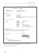
iDP-562 User’s Manual 1996.01.22(10-DCL)11 Declaration of Conformity Manufacturer's Name : Manufacturer's Address : Japan CBM Corporation : 1-1-7, Okubo, Shinjuku-ku, Tokyo 169, Japan Declare the Product Product Name Model Number (s) Dot Matrix Printer iDP-562 Series (iDP-562RSL2, iDP-562RSL, iDP-562CNL, iDP-562RS, iDP-562CN) (S.NO.
iDP-562 User’s Manual IMPORTANT SAFETY INSTRUCTIONS * Read all of these instructions and save them for future reference. * Follow all warnings and instructions marked on the product. * Unplug this product from the wall outlet before cleaning. Do not use liquid or aerosol cleaners. * Use a damp cloth for cleaning. * Do not use this product near water. * Do not place this product on an unstable cart, stand, or table. The product may fall, causing serious damage to the product.
iDP-562 User’s Manual *iDP562-RSL/RS, iDP562-CNL/CN type IMPORTANT: This equipment has been tested and found to comply with the limits for a Class A digital device, pursuant to Part 15 of the FCC Rules. These limits are designed to provide reasonable protection against harmful interference when the equipment is operated in a commercial environment.
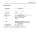
iDP-562 User’s Manual Contents 1. Outline.................................................................................................................................................................... 6 1.1 Features ............................................................................................................................................................ 6 1.2 Accessories ...................................................................................................................
iDP-562 User’s Manual 1. Outline iDP562 is a dot impact printer. The compact and light weight printer is sufficiently provided with various functions in order to suffice the requirements of personal computers. This printer is useful especially for receipts and data recording on normal and carboned roll papers. Use this printer properly after reading carefully the manuals of the printer and your computer. 1.1 Features The printer features the following: 1. Compact dot matrix printer 2. Light weight 3.
iDP-562 User’s Manual 2. Basic Specifications 1 2 3 4 5 6 7 8 9 10 11 Printing Method Printing Speed Character Column Capacity Character Size Line Spacing Line Feed Speed Character Code Paper Ink Ribbon Cassette Voltage 12 Power 13 Weight 14 Dimensions 15 Interface 16 Operating Temperature 17 Storage Temperature :Serial Dot Matrix :74 LPM with 40column, 235 LPM with 5 column (approx..) :7 ´ 5 (Dots) :40 column :2.75 mm (H) ´ 1.25 mm (W) :5.5 mm :6.2 lines / second approx..
iDP-562 User’s Manual 3 .Appearance and Parts Name 3.1 Appearance and Parts name (Front view) (Fig.1) (Rear view) (Fig.
iDP-562 User’s Manual 3.2 Description on Each Part 1 Power Plug 2 Power Switch 3 Power Lamp 4 SEL Lamp 5 ALM Lamp 6 LF Switch 7 SEL Switch 8 Printer Cover 9 Interface Connector CITIZEN Insert this plug in the plug socket under the prescribed voltage. As the power switch is turned on, initializing performance of the printer starts and the print head returns to the left end (home position). The lamp lights up as power switch is on and turns off when the switch is off.
iDP-562 User’s Manual 4. Operation 4.1 The Ribbon Cassette Installation Before inserting the ribbon, disconnect the power source. If the printing has been continued for many hours, be careful not touch printer head as it might be hot. 1) 2) 3) Remove the printer cover. While inserting the ribbon into the space between the print head and the ribbon guide, press the cassette into the holder unit it clicks into place. (Ref. to Fig.
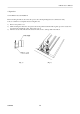
iDP-562 User’s Manual 4.2 Loading the Paper (Fig.5) Paper Insertion procedures 1. Turn OFF the power switch. 2. Remove the printer cover. 3. Cut the paper in right angle to its longitudinal center line as shown in Fig. 6. 4. Insert the paper into insertion inlet on the rear side of the printer. 5. Turn on the power switch. And then press LF switch to forward the paper into the printer. 6. Fix the roll paper at paper holder and set the printer cover. 7.
iDP-562 User’s Manual 4.3 Testing Your Printer IDP562 Model has a self-printing pattern in order to check the printing function. Take the following procedures to test your printer. 1. Set the power switch. 2. Turn off the power switch. 3. Turn on the power switch while pressing the LF switch., then release the LF switch. 4. To stop the printing, turn off the power switch. After 9 lines are printed, the printing is stopped automatically.
iDP-562 User’s Manual 5. Serial Interface 5.1 Serial Specifications (1) Synchronous Asynchronous (2) Baud rate 150, 300, 600, 1200, 2400, 4800, 9600 BPS One of the above baud rates is selected by users. (3) Data Format Start bit: 1 BIT Data bit: 7 or 8 BIT Parity bit: Odd number parity, even number parity or no parity check, one of which is selected by users.
iDP-562 User’s Manual 5.2 Setting of DIP Switch and SLIDE Switch Following function are available by setting DIP switch and SLIDE Switch. Selection of “CR” and “LF” code function. Please refer to the table below. DSW-1 DSW-2 DSW-3 CR and LF code When CR code comes are valid function. immediately after full When the buffer is blank. *OFF CR code is selected buffer printing by the DSW-2 and 3.
iDP-562 User’s Manual 5.3 Connectors and Signals Signal Pin 1 7 3 20 Return Line 14 25 17 23 24 Signal Name FG SG RD DTR Direction of Signal FAULT ¬ ® ¬ RD DTR A®B ¬ Function RS232C CURRENT LOOP TTL Frame GND GND Input DATA BUSY signal O O O O ALARM signal O O Input DATA BUSY signal O O A: Computer B: Printer Notes: 1. Signal of RS-232C conforms to EIA RS-232C level. 2. Signal of CURRENT LOOP should be restricted within 10 ~ 20 mA. 3. Keep signal pin No.
iDP-562 User’s Manual 5.5 Current Loop and TTL 5.5.1 Interface Loop (a) Current Loop Input (RD) Printer side Computer side Output (DTR) Note: Resistance should be set so that Current Loop is restricted within 10 ~ 20 mA. (b) TTL Input (RD) Printer side Computer side Equivalent to 7407 Output (DTR FAULT) Note: Output is open collector.
iDP-562 User’s Manual 5.5.2. Setting of Preset jumper Following function are available by setting preset jumper 1 ~ 6. Please turn off power and remove a bottom case before setting.
iDP-562 User’s Manual Preset jumper Preset Jumper 1 2 3 4 5 RS-232C A A A × A Mode CURRENT LOOP TTL × B × B B B B A × B ´ : Both A and B can be set. B position A position A 6 CITIZEN B DATA can be transferred at DTR = SPACE A (RS-232C / TTL level) DATA can be transferred at DTR = MARK (CURRENT LOOP) DATA can be transferred at DTR = MARK B (RS-232C / TTL level) DATA can be transferred at DTR = SPACE (CURRENT LOOP) At shipping all of preset jumper are set as A.
iDP-562 User’s Manual 5.6 DATA Construction 5.6.1 Serial Data format 1. Start BIT 2. DATA BIT (+ Parity BIT) 3. Stop BIT (1 ~ 2 BIT) (1) START BIT At 1 / 2 BIT after (a), signal level is checked out, (b). When signal level is MARK, continuous search for START BIT is made for the next bit. (2) DATA BIT + PARITY BIT DATA BIT and PARITY BIT are checked out every 1 / 2 BIT from the half point of START BIT, (b). Signal level of these points (MARK = 1, SPACE = 0) are read as input DATA.
iDP-562 User’s Manual 5.6.2. Detection System for Error The printer detects PARITY and FRAMING ERROR. ALARM (ALM) LAMP informs the user error occurrence. When any error is detected, the printer deletes the wrong DATA and waits for new DATA, ALM LAMP can be put out by depressing SEL switch. Framing Error Framing error occurs when SPACE signal is checked out at STOP BIT. ALM LAMP informs the user this error and the wrong data is neglected by the printer.
iDP-562 User’s Manual (2) Input Control for Double Buffer Double buffer transfer is made as follows. 1. The computer transfers 1st and 2nd BYTE of DATA after checking READY condition. 2. The printer continues BUSY condition for receiving 2nd BYTE of DATA. 3. The computer transfers 3rd BYTE of DATA after checking READY condition. The printer expects Double Buffer transfer at the first stage. Therefore, after completion of 1st BYTE of DATA reception, the printer waits for 2nd BYTE of DATA.
iDP-562 User’s Manual 6. Parallel Interface 6.1 Description on Input / Output Signals (a) Input signals to printer O DATA 1 …. 8 bit parallel input Data Signal, Logic “1” represent HIGH level. DATA 2 DATA 3 DATA 4 DATA 5 DATA 6 DATA 7 DATA 8 O STB ……. This is a strobe for reading-in the data signal. This signal is normally HIGH. The data signal is clocked-in when STB is made LOW by the host computer. (b) Output signals from printer O ACK …….
iDP-562 User’s Manual 6.2 Setting the Dip Switch IDP562CNL / CN has Dip Switch with which you can select the followings to meet your computer’s function. Selection of “CR” and “LF” code function. Please refer to the table below. DSW-1 CR and LF code are valid function. *OFF CR code is selected by the DSW-2 and 3. ON CR code is ignored LF code is valid. LF code is selected by the DSW-2 and 3. DSW-2 When CR code comes immediately after full buffer printing DSW-3 When the buffer is blank.
iDP-562 User’s Manual 6.3 Connector and Pin Assignment PIN NO. Signal Name 1 STB DATA 1 2 2 3 3 4 4 5 5 6 6 7 7 8 9 DATA 8 10 11 12 13 14 15 16 17 18 ACK BUSY GND SLCT GND GND PIN NO.
iDP-562 User’s Manual 6.4 Electric Characteristics (a) Input Signal Level All the input / output signals are of TTL level. “HIGH” level 2.0 V MIN “LOW” level 0.8 V MAX (b) Output Signal Level “HIGH” level 2.4 V MIN “LOW” level 0.4 V MAX (c) Input / Output Conditions All the input signal are pulled up by 1 K ohms. (Fig. 7) (Fig.7) All the output signals are pulled up by 3.3 K ohms. (Fig. 8) (Fig.
iDP-562 User’s Manual 6.5 Timing Chart (1) Input Data and print timing T1, T2, T3 T4 T5 T6 0.5ms MIN 100 ns MAX 7m TYP 1100 ms MAX 400 m MAX When data is stored input buffer. (2) FAULT and SEL switch T1 0.
iDP-562 User’s Manual 7. Control Code Control codes are the same for 7 BIT DATA and 8 BIT DATA except SI & SO code. 7.1 SI & SO Code Symbol 8 BIT DATA SI Standard character designation (Same as US) SO Enlarged character designation (Same as RS) 7 BIT DATA Designation of SI side character Designation of SO side character 7.2 Function Code Symbol LF CR RS Code Function ( Hexadecimal) 0A Feeds a new line after printing. 0D Feeds a new line after printing.
iDP-562 User’s Manual 7.3 Input Data Format The input data to the printer is made by the codes listed in the Character Code Table. 1 Standard Character print Mode Designation US(1F) DATA Designation of standard character print mode is made immediately after power-on and initialization or after print. Therefore US code can be omitted. In addition, when the data of 40 characters (standard character mode) is input in one line, an automatic line feed is carried out after printing (full buffer print).
iDP-562 User’s Manual 4 Graphic Print Mode Designation ESC(1B) K(4B) n1 n2 DATA Input ESC K (1B 4B) at the top of the line and then input Graphic Print Data, which is converted to binary, into n1. After that, input dummy data in n2. If it is also the Graphic Print in the next line, ESC K n1 n2 should be input once again before the data. The number for Graphic Print Data should be: 1 £ n1 £ 240 Any numbers other than the above comes to 240.
iDP-562 User’s Manual 6 Paging designation and page length designation ESC(1B) C(43) n Input ESC C (1B, 43) at the top of the line and next input n, which are integers. With this code, the length (number of line) per page can be set, and paging action is started, and the space of three lines are left at the both top and bottom of the page, n should be: 14 £ n £ 120 Otherwise, it comes to 66. The paging can be released by ESC O (1B, 4F). 7 Form Feed FF(0C) With this code, paper feed goes on.
iDP-562 User’s Manual 8. Initial Setting Followings are automatically set after Power-on or depressing SEL switch (After ALARM condition). 1. 2. 3. 4. 5. 6. 7. 8. A printer head returns to its home position. Printer becomes SELECT (ON-LINE) condition. (*1) Print buffer function is cleared. Standard character mode is set. 66 per lines per page is set. The first line is set at the present line. Designation of reverse and red printing is cleared. For 7 BIT DATA, character code of SI is applied. *1.
iDP-562 User’s Manual 9.
iDP-562 User’s Manual (2) Foreign Character Designation of characters can be made for four languages by ON and OFF of Dip switch.
iDP-562 User’s Manual (3) Character Code Table for 7 BIT DATA SI Side CITIZEN SO Side 34
iDP-562 User’s Manual 10. Maintenance With respect to maintenance: The mechanical part of the printer must be free from dirt and dust. Remove the printer cover periodically to clean printer mechanism with soft brush to eliminate any dirt and dust.