DOT MATRIX PRINTER MODEL iDP3420 iDP3421 iDP3423 User’s Manual
iDP3420/3421/3423 User’s Manual Declaration of Conformity This printer conforms to the following Standards: Low Voltage Directive 73/23/EEC, 93/68/EEC and the EMC Directive 89/336/EEC, 92/31/EEC, 93/68/EEC. LVD : EN60950 EMC : EN55022 Class A EN61000-3-2 EN61000-3-3 EN55024 This declaration is applied only for 230V model. CITIZEN is a registered trade mark of CITIZEN WATCH CO., LTD., Japan CITIZEN es una marca registrada de CITIZEN WATCH CO., LTD.
iDP3420/3421/3423 User’s Manual IMPORTANT SAFETY INSTRUCTIONS • • • • • • • • • • • • • Read all of these instructions and save them for future reference. Follow all warnings and instructions marked on the product. Unplug this product from the wall outlet before cleaning. Do not use liquid or aerosol cleaners. Use a damp cloth for cleaning. Do not use this product near water. Do not place this product on an unstable cart, stand or table. The product may fall, causing serious damage to the product.
iDP3420/3421/3423 User’s Manual WICHTIGE SICHERHEITSANWEISUNGEN • • • • • • • • • • • Lesen Sie die nachfolgenden Anweisungen sorgfältig durch und bewahren Sie sie auf. Befolgen Sie alle auf dem Drucker vermerkten Hinweise und Anweisungen. Vor dem Reinigen grundsätzlich Stecker aus der Steckdose ziehen. Keine Flüssigkeiten oder Aerosolreiniger benutzen. Nut mit einem feuchten Tuch abwischen. Der Drucker darf nicht in der Nähe von Wasser aufgestellt werden.
iDP3420/3421/3423 User’s Manual IMPORTANT: This equipment generates, uses, and can radiate radio frequency energy and if not installed and used in accordance with the instruction manual, may cause interference to radio communications. It has been tested and found to comply with the limits for a Class A computing device pursuant to Subpart J of Part 15 off FCC Rules, which are designed to provide reasonable protection against such interference when operated in a commercial environment.
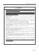
iDP3420/3421/3423 User’s Manual 1. Prior to using the equipment, be sure to read this User's Manual thoroughly. Please keep it handy for reference whenever it may be needed. 2. The information contained herein ma y be changed without prior notice. 3. Reproduction of part or all of this User's Manual without permission is strictly prohibited. 4. Never service, disassemble, or repair parts that are not mentioned in this User's Manual. 5.
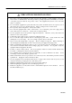
iDP3420/3421/3423 User’s Manual SAFETY PRECAUTIONS ----- BE SURE TO OBSERVE In order to prevent hazards to an operator or other persons and damage to property, be sure to observe the following precautions. • The following describes the degrees of hazard and damages that can occur if the given instructions are neglected or the equipment is incorrectly operated. WARNING Negligence of this precaution may result in death or serious injury.
iDP3420/3421/3423 User’s Manual WARNING • Never handle the equipment in the following manners, as it may break, become out of ord er, or overheat causing smoke and resulting in fire or electric shock. If the equipment is used in an abnormal condition, such as when broken, then problems, smoke emission, abnormal odor/noise, and fire can result. If an abnormal condition exists, be sure to turn off the power, disconnect the power plug from a plug socket, and contact our dealer.
iDP3420/3421/3423 User’s Manual PRECAUTIONS FOR INSTALLATION • Do not use or store the equipment in a place exposed to fire, moisture, or direct sunlight, or in a place near a heater or a thermal device where the prescribed operating temperature and humidity are not met, or in a place exposed to much oil, iron powder, or dust. The equipment may become out of order, emit smoke, or catch fire.
iDP3420/3421/3423 User’s Manual PRECAUTIONS FOR HANDLING Do not handle the equipment in the following manners, because problems may result. • Do not use a power supply other than the specified AC adapter. • Do not print when there is no recording paper or ink ribbon set in the equipment. The print head may be damaged • Be careful not to drop foreign substances, such as clips, pins, and screws, into the mainbody. • Do not spill any liquid or spray any chemical-containing liquid over the equipment.
iDP3420/3421/3423 User’s Manual DAILY MAINTENANCE • Prior to starting maintenance work, be sure to turn off the main body. • Use a dry soft cloth to wipe off stains and dust from the surfaces of the main body case. soiling, dip the cloth in water and wring it, for wiping off the soil. Never use org For severe anic solvents, such as alcohol, thinner, trichlene, benzene, ketone, or chemical dusters. • If the equipment is contaminated with paper powder, use a soft brush to clean it.
iDP3420/3421/3423 User’s Manual CONTENTS 1. OUTLINE .............................................................................................................................................................. 1 1.1 Features ......................................................................................................................................................... 1 1.2 Unpacking ................................................................................................................
iDP3420/3421/3423 User’s Manual 4.14 Print Duty.....................................................................................................................................................20 5. DIP SWITCH SETTING.................................................................................................................................... 21 5.1 Location of DIP Switch..............................................................................................................................
iDP3420/3421/3423 User’s Manual 11. DRAWER KICK-OUT CONNECTOR ........................................................................................................... 38 11.1 Specifications of Drawer Kick-Out Connector ...............................................................................................38 11.2 Connector's Pin Configuration.......................................................................................................................38 11.3 Drive Circuit............
iDP3420/3421/3423 User’s Manual <<< German >>> 4. BETRIEB ........................................................................................................................................................... 138 4.1 Anschluß des Netzkabels ..................................................................................................................................138 4.2 Anschluß des Schnittstellenkabels ..........................................................................................
iDP3420/3421/3423 User’s Manual 1. OUTLINE This is a small-size dot impact printer developed for various data communication terminals, POS terminals, kitchen-use printers, bank card, terminals, and so on. Its abundant built-in features allow you to widely use this printer for different applications. Prior to using it, read and understand this manual thoroughly. 1.
iDP3420/3421/3423 User’s Manual 2. 2.1 BASIC SPECIFICATIONS Model Classifications The printer model is classified by the following designation method.
iDP3420/3421/3423 User’s Manual 2.2 Basic Specifications Model Item Printer mechanism Print method Print width Print head Print speed Print columns Character size Character types iDP3420 iDP3421 iDP3423 DP-410 series (CITIZEN) Serial dot impact method (Bidirectional print) 64 mm 9 pins Approx. 3 lines/second (At single-color continuous print) 40 or 42 columns (Selectable with the DIP switch) 1.31 mm(W) × 3.
iDP3420/3421/3423 User’s Manual 2.3 Paper Specifications 2.3.1 Recommended Paper • Type : Normal paper and non-carbon paper • Paper width : 76 +/- 0.5 mm • Paper thickness : Single-sheet paper Copying paper --- 45 to 55 kg/1,000 sheets/1,091 × 788 mm; --- Non-carbon paper, 1 original + 1 copy, Total thickness 0.2 mm or less • Roll diameter : φ83 mm or less (Normal paper) φ60 mm or less (Normal paper only for journal) (iDP3423) φ80 mm or less (Copying paper) (iDP3423) • Core 2.3.
iDP3420/3421/3423 User’s Manual 3. 3.
iDP3420/3421/3423 User’s Manual 3.
iDP3420/3421/3423 User’s Manual 3.
iDP3420/3421/3423 User’s Manual 4. 4.1 OPERATION Connecting the Power Cord 1. Turn off the Power switch. 2. Connect a power cord connector to the power connector located on the back of the printer. 3. Connect a power cord plug to a plug socket where the specified voltage is available. CAUTIONS : • Use the AC power supply different from the one used for any noise-generating device. • When disconnecting the power cord, be sure to hold its plug.
iDP3420/3421/3423 User’s Manual 4.2 Connecting the Interface Cable 1. Turn off the power. (Mating side included) 2. Check the top and bottom of the cable terminals, and connect to the interface connector. 3. Secure the cable terminals. Serial interface : Tighten screws to secure. Parallel interface : Turn clamps to secure. 4. Connect the interface cable to the computer.
iDP3420/3421/3423 User’s Manual 4.3 Attaching the Ferrite Core to the Interface Cable 1. Turn off the power.(Mating side included) Ferrite Core 2. With a regular screwdriver, unlatch and open the ferrite core. Interface Cable 3. Attach the ferrite core to the interface cable so that its end face will be within up to 5 cm. Ferrite Core Within 5 cm 4. Secure the arm of the ferrite core onto the cable with a fastener so that the ferrite core will not move.
iDP3420/3421/3423 User’s Manual 4.4 Connecting the Drawer Kick-Out Connector 1. Turn off the power. 2. Check the top and bottom of the drawer kick-out cable connector and connect it to the drawer kick-out connector located on the back of the printer. 3. Screw the grounding cable of the drawer to the grounding terminal of the printer. CAUTION: • Connect only the prescribed drawer (Solenoid) to the drawer kick -out connector. Drawer Kick-Out Connector Drawer Kick-Out Cable Connector Earth Terminal 4.
iDP3420/3421/3423 User’s Manual 4.6 Setting the Cassette Ribbon (1) Open the printer cover. (2) Open the auto cutter. (iDP3421/3423) (3) If the ribbon is slackened, turn the knob in the arrow-indicated direction to give the tension to it before setting. (4) While putting the ribbon in between the head cover and platen, push the locking claws into the holder of the printer. (5) Turn the knob of the cassette ribbon in the arrow -indicated direction to eliminate slackness of the ribbon.
iDP3420/3421/3423 User’s Manual 4.7 Inserting the Paper 4.7.1 Inserting the Paper (iDP3420/3421) (1) Put your hands in the concave parts on both sides of the printer cover, and open it until it comes to a stop. (2) Cut the end of the paper roll at close to a right angle. CAUTION : • Be sure to use the specified paper roll. • Use of unspecified paper may adversely affect print quality, printer service life, and so on. • The printer cover is not detachable.
iDP3420/3421/3423 User’s Manual Paper Roll Setting Direction 14 CITIZEN
iDP3420/3421/3423 User’s Manual 4.7.2 Inserting the Paper Roll (Duplicable 2-sheet Paper) (iDP3423) 1. See Steps 1 to 6 in 4.7.1 Inserting the Paper. 2. Press the FEED switch to feed the paper until the end of the paper comes out of the paper outlet port of the auto cutter by about 25 cm. 3. Open the auto cutter and pull out the paper roll from it. 4. Thread the journal paper (Copying paper) between the auto cutter and platen. 5.
iDP3420/3421/3423 User’s Manual 4.7.3 Removing the Wound Paper Roll (iDP3423) 1. Open the printer cover. 2. Remove the paper roll by cutting it halfway or pushing the paper free lever in the arrow-indicated direction. 3. Detach the winding reel. 4. Pull out a flange from one side of the winding reel. 5. Pull out the paper roll from the winding reel. Flange Winding Reel Paper Roll (Receipt Paper) 4.8 Adjusting the Paper Near End Sensor 1. Close the printer cover. 2.
iDP3420/3421/3423 User’s Manual 4.9 How to Remove Remaining Paper Roll (1) Open the printer cover. (2) Open the auto cutter. (iDP3421/3423) (3) Pushing the paper-free lever in the arrow direction, pull out the pape r roll. (4) Close the auto cutter. (iDP3421/3423) CAUTION : • When pulling out the paper (Forward/Reverse direction), be sure to operate the paper-free lever. • When closing the auto cutter, do so gently not to give a shock. Paper-Free Lever 4.
iDP3420/3421/3423 User’s Manual 4.11 Unlocking the Cutter (iDP3421/3423) 1. Open the printer cover. 2. Press the FEED switch. The auto cutter is initialized to return its blade and clear an alarm. 3. If the paper is jamming, eliminate the jamming paper completely, seeing "4.9 Removing Paper Jam." 4. If the alarm still cannot be cleared, turn off the power and open the auto c utter. 5. You can see an emergency knob through a small hole in the back of the auto cutter. Using tweezers, screwdriver, etc.
iDP3420/3421/3423 User’s Manual 4.12 Operation Panel and Display of Error 1. POWER lamp (Green) This lamp is illuminated when the power is supplied. 2. ERROR lamp (Red) This lamp is illuminated or blinks to indicate each error. Error Indication Mechanical Error ERROR Lamp Quick blinking Paper End Buzzer Resetting Method Sounds continuously for Reset the Power approx. 1 second switch. Repeats a short 3-time Set a new paper roll. sound twice at intervals of 0.5 second.
iDP3420/3421/3423 User’s Manual 4.13 Operation Flow at Power-on Power-on OFF Feed SW ? ON Buffer data YES "Clear Data in Buffer" Yes(FEED SW) and Enlarged Red Print NO 1 Sec. Passed NO 1 Sec. Passed NO YES OFF YES OFF FEED SW ? (CONTINUE) FEED SW ? (AGAIN) ON ON Prints "=Hexadecimal Dump=." Dump Mode Test Print Buffer Data Input Buffer Clear NO YES Prints "Power Down(Data in Buffer)" in Red, Followed by Buffer Contents.
iDP3420/3421/3423 User’s Manual 5. 5.1 DIP SWITCH SETTING Location of DIP Switch 1. Turn off the power. 2. Open the printer cover. 3. If the paper roll has been set, remove it from the paper holder. 4. Detach the DIP switch cover. The DIP switch can be found at the location shown in the figure below.
iDP3420/3421/3423 User’s Manual 5.2 DIP Switches Setting 1) DIP Switch 1 No. Function DS1-1 Auto cutter International characters DS1-2 DS1-3 ″ DS1-4 ″ DS1-5 Paper used DS1-6 CR mode DS1-7 Columns DS1-8 Buffer size DS1-9 Operation mode DS1-10 ″ *1, *3 : Depends on the type. *2 : Depends on the destination.
iDP3420/3421/3423 User’s Manual 2) DIP Switch 2 No.
iDP3420/3421/3423 User’s Manual 6. PRESET JUMPER SETTING 6.1 Location of Preset Jumper (1) Turn off the power. (2) Remove a cassette ribbon. (3) Remove the top cover. The preset jumper is located as shown in the figure below. Serial Interface 6.
iDP3420/3421/3423 User’s Manual 7. MODE SETTING METHOD This printer has the CBM, Star, and ESC/POS mode. Any desired mode can be selected and set according to your need. (1) Setting method • See 5. DIP SWITCH SETTING. • Seeing the settings of the DIP switch segments 1-9 and 1-10 and those of the preset jumper, set each mode.
iDP3420/3421/3423 User’s Manual 8. 8.1 INPUT BUFFER BACKUP FUNCTION Buffer Size With the DIP switch, you can set either 6 K bytes or 256 bytes. DIP switch segment 1-8 ON → 6K bytes OFF → 256 bytes 8.2 Input Buffer Backup Even if the power is turned off or fails during the printing process, the data in the input buffer will be saved.
iDP3420/3421/3423 User’s Manual 9. PARALLEL INTERFACE 9.1 Specifications • Data input system : 8-bit parallel system (DATA1 to DATA8) • Control signals : ACK, BUSY, STB, FAULT, SELECT, RESET, COMPULSION • Applicable connectors : Printer side --- 57LE-40360 (Equivalent to anphenol), Cable side 9.2 --- 57-30360 (Ditto) Connector's Pin Configuration Mode No.
iDP3420/3421/3423 User’s Manual 9.3 Input and Output Signals 9.3.1 Input and Output Signals (1) Input signals to the printer • DATA : An 8-bit parallel signal. (Positive logic) • STB : A strobe signal to read the 8-bit data. (Negative logic) • RESET : A signal to reset the printer from the outside. (Negative logic) (2) Output signals from the printer • ACK : An 8-bit data request signal. A pulse signal output at the end of the BUSY signal.
iDP3420/3421/3423 User’s Manual 9.3.2 Electrical Characteristics (1) Input signal level All the input signals are at the TTL level. "HIGH" level : 2.0 V at minimum "LOW" level : 0.8 V at maximum (2) Output signal level All the output signals are at the TTL level. "HIGH" level : 2.4 V at minimum "LOW" level : 0.4 V at maximum (3) Input and output conditions All the input signals are pulled up at 3.3 kΩ. [Printer Side] [Host Side] Twisted Pair Wire All the output signals are pulled up at 3.3kΩ.
iDP3420/3421/3423 User’s Manual 9.3.3 Timing Chart (1) Data input and printing timing 9.3.4 T1, T2, T3 : 0.5 µs MIN T4 : 270 ns MAX T5 : 2.3µs TYP T6 : 500 ms MIN (At power-on) Data Receiving Control When the BUSY signal is at "LOW," the printer can receive the data from the host, but when at "HIGH," it cannot.
iDP3420/3421/3423 User’s Manual 10. SERIAL INTERFACE 10.
iDP3420/3421/3423 User’s Manual 10.2 Connector's Pin Configuration Mode No. 1 2 3 4 5 6 7 8 9 10 11 12 13 14 15 16 17 18 19 20 21 22 23 24 25 Cautions: CBM Star ECS/POS FG TXD RXD ← ← ← ← ← ← ← RTS DSR GND ← PE (HI-LEVEL) FAULT RCH ← GND FAULT mTXD mRXD ← DTR ← RESET 1. 2. An RS-232C signal is based on the EIA RS-232C. When the data is not being transferred, the received data should be always maintained as a mark.
iDP3420/3421/3423 User’s Manual 10.3 Input and Output Signals 10.3.1 Input and Output Signals (1) RXD This is a serial received data signal. When a framing error, overrun error, or parity error occurs, that data is printed as "?". (2) DTR When this signal is Ready, write the data or a command. error results, ignoring the previous data. printing.
iDP3420/3421/3423 User’s Manual (7) RTS This signal is turned to Space when the printer is turned on. (8) RCH When the printer is ready to receive, this signal is turned to Space. This signal line is the same as DTR. (9) mTXD TXD signal for the diode gate. (10) mRXD RXD signal for the diode gate. (11) FG This is a Frame Ground signal. (12) GND This is a common ground on the circuit.
iDP3420/3421/3423 User’s Manual 10.3.2 Data Configuration t Mark b0, b1, b2, • • • • Space (1) (2) (3) (1) Start Bit (2) Data Bit (+ Parity Bit) (3) Stop Bit (1 or More) (1) Start bit After a lapse of 1/2 bit from a mark-to-space fall edge, the state is read again, and if it is a space, it is recognized as the start bit. If it is a mark, it is assumed neither the start bit nor an error, and it is attempted to detect the start bit again.
iDP3420/3421/3423 User’s Manual 10.3.3 Error Detection A parity error, framing error, and overrun error are detected. When an error is detected, that data is stored in the buffer as "?". (1) Framing error This error results when a space is detected in detecting the stop bit. That data is stored in the buffer as "?". (2) Parity error If a parity check has been specified and an error is detected at the time of parity check, that data is stored in the buffer as "?".
iDP3420/3421/3423 User’s Manual 10.3.6 Electrical Characteristics (1) RS-232C circuit Input (RXD, DSR, mRXD) [Printer Side] [Host Side] Mark=(-8V) : Stop bit RXD Space=(+8V): Start bit Equivalent MAX232 Output (DTR, TXD, mTXD, RCH, RTS, FAULT) Equivalent to MAX232 Mark=(-8V): At Busy Mark=(-8V): 1 DTR TXD Space=(+8V): At Ready Space=(+8V): 0 (2) Others • RESET : A signal to reset the entire printer. • PE : A signal to show that the paper has run out.
iDP3420/3421/3423 User’s Manual 11. DRAWER KICK-OUT CONNECTOR 11.1 Specifications of Drawer Kick-Out Connector (1) Drawer kick-out drive signal Parallel ----- Can be learned at the no. 34 pin of the interface connector Serial ----- Provided with a command to learn the status in the Star and ESC/POS modes. (2) Electrical characteristics 1) Drive voltage: 24 V DC 2) Drive current: 0.8 A at maximum (Within 510 ms) 3) Switch signal: Signal level "L" = 0 to 0.5 V "H" = 3 to 5 V 11.
iDP3420/3421/3423 User’s Manual 12. MAINTENANCE AND SERVICE For the information on maintenance and service, please contact our dealer.
iDP3420/3421/3423 User’s Manual 13. PRINT CONTROL FUNCTIONS 13.1 CBM Mode 13.1.
iDP3420/3421/3423 User’s Manual 13.1.2 Description of Items XXXX ALL [Function] Command name [Code] A row of command constituent code is represented by a hexadecimal number with < >H, binary number with < >B, and a decimal number with < >. [ ]k means a repeat count of k-times. [Range] Describes an argument value (Setting range) for the command. [Outline] Describes a command function. [Caution] Describes a caution as required.
iDP3420/3421/3423 User’s Manual Details FF n [Function] n-line paper feed [Code] <0C>H n [Range] 1 ≤ n ≤ 127 [Outline] This command feeds the paper by n-lines. You can set n = 1 to 127 lines. If the print buffer contains the data, use of this command feeds the paper by n-lines after printing the data. Setting n = 0 does not feed the paper.
iDP3420/3421/3423 User’s Manual SI [Function] Canceling the double width character [Code] <0F>H [Outline] This command cancels the double width characters set with SO. The data following this command are printed in the ordinary character width. LF [Function] Printing and paper feed [Code] <0A>H [Outline] If the print buffer contains the data, this command will feed the line after printing. If not, the command only feeds the line.
iDP3420/3421/3423 User’s Manual DC1 [Function] Initializing the printer [Code] <11>H [Outline] This command initializes the printer. The input buffer is not cleared. The settings of the DIP switch segments are not re-read. DC2 [Function] Specifying/Canceling the inverted character [Code] <12>H [Outline] This command selects/deselects the inverted characters. beginning of one line. Otherwise, it is overridden.
iDP3420/3421/3423 User’s Manual DC3 [Function] Specifying the red print [Code] <13>H [Outline] This command specifies red-color characters. All the characters in one line are printed in red by prefixing the print data with this command and sending it to the printer. When you want to use red characters, use this command for each line. CAN [Function] Canceling the print data [Code] <18>H [Outline] This command clears the print data in the lines entered prior to this command.
iDP3420/3421/3423 User’s Manual ESC "∗" n1 n2 [Function] Specifying the bit image mode [Code] <1B>H <2A>H n1 n2 [Range] 1 ≤ n1 + 256 × n2 ≤ 378 [Outline] This command allows printing in the bit image mode. Divide the number of dots printed by 256 and assume its quotient to be n2 and remainder to be n1. Therefore, the number of horizontal dots will be n1 + 256 × n2. If the bit image data is entered beyond the dot positions printable in one line, the surplus data will be discarded.
iDP3420/3421/3423 User’s Manual ESC "1" [Function] Setting the 1/9-inch line feed width [Code] <1B>H <31>H [Outline] This command sets the line feed width to 1/9 inch. ESC "2" [Function] Setting the 2/9-inch line feed width [Code] <1B>H <32>H [Outline] This command sets the line feed width to 2/9 inch. ESC "3" [Function] Setting the 1/6-inch line feed width [Code] <1B>H <33>H [Outline] This command sets the line feed width to 1/6 inch(Default).
iDP3420/3421/3423 User’s Manual ESC "N" n [Function] Specifying the perforation skip [Code] <1B>H <4E>H n [Range] 1 ≤ n ≤ 126 [Outline] This command feeds(Skips) the lines specified with n without printing. However, you cannot specify beyond the length of one page. ESC "O" [Function] Canceling the perforation skip [Code] <1B>H <4F>H [Outline] This command cancels perforation skipping operation.
iDP3420/3421/3423 User’s Manual ESC "t" n [Function] Selecting the character code table [Code] <1B>H <74>H n [Range] 0 ≤ n ≤ 255 [Outline] This command selects Page-n of Character CodeTable. [Default] Depends upon DIP switch setting.
iDP3420/3421/3423 User’s Manual ESC BEL n1 n2 [Function] Setting the external device drive pulse width [Code] <1B>H <07>H n1 n2 [Range] 1 ≤ n1 ≤ 127 [Outline] This command sets the power-on time to drive an external device (Cash drawer). 1 ≤ n2 ≤ 127 Power-on time = n1 × 10 (ms) Delay time = n2 × 10 (ms) To actually drive the drawer, use the and commands.
iDP3420/3421/3423 User’s Manual FS [Function] Driving command B drawer-1 [Code] <1C>H [Outline] This command drives the drawer connector No. 2 pin under the condition set with the n1 n2 command. SUB [Function] Driving command for drawer-2 [Code] <1A>H [Outline] As soon as this command is received, the drawer connector no. 5 pin is driven. power-on time is 200 ms ON and 200 ms OFF stationary. The The drawers 1 and 2 cannot be driven simultaneously.
iDP3420/3421/3423 User’s Manual ESC "P" 0 (iDP3421/3423 only) [Function] Full cut [Code] <1B>H<50>H<00>H [Outline] This command fully cuts the paper. ESC "P" 1 (iDP3421/3423 only) [Function] Partial cut [Code] <1B>H<50>H<01>H [Outline] This command partially cuts the paper. ESC "R" n [Function] Selecting the international character set [Code] <1B>H <52>H n [Range] 0 ≤ n ≤ 10 [Outline] This command selects the international characters according to the value of n.
iDP3420/3421/3423 User’s Manual ESC "&" <0> n1 n2 [m0 m1 ... m5 m6 m7 m8 m9] n2 - n1 + 1 [Function] Defining the Download character set [Code] <1B>H <26>H <00>H n1 n2 [m0 m1 ... m5 m6 m7 m8 m9] n2 - n1 + 1 [Range] 32 ≤ n1 ≤ n2 ≤ 255 [Outline] This command defines he download characters. m0 = 0 or m0 = 128 and n2 is to end definition, respectively. n1 is a character code to start definition When defining only one character, set n1 = n2. You can define the ASCII codes ranging from 32 to 255.
iDP3420/3421/3423 User’s Manual ESC "%" n [Function] Specifying/Canceling the download character set [Code] H <25>H n [Outline] This command selects/deselects the download character set. The download characters cannot be printed by simply defining them with the above-mentioned ESC & 0 command. To print them, send this command to the printer.
iDP3420/3421/3423 User’s Manual ESC DC3 n [Function] Printing the message [Code] <1B>H <13>H n [Range] 1 ≤ n ≤ 10 [Function] This command prints a message. If the value of n is specified beyond the range, the message will not be printed. ESC "y" n [Function] Setting the print lines after paper near end detection [Code] <1B>H<79>H n [Range] 0 ≤ n1 ≤ 255 [Outline] This command sets the number of print lines after paper near end detection.
iDP3420/3421/3423 User’s Manual ESC DC2 n1 n2 [Function] Deleting the download character, message, bit image [Code] <1B>H <12>H n1 n2 [Range] 0 ≤ n1 ≤ 3 0 ≤ n2 (Specify 0 at n1 = 0) (1 ≤ n2 ≤ 10 at n1 = 1) (32 ≤ n2 ≤ 255 at n1 = 2) (Specify 0 at n1 = 3) [Outline] This command deletes the downloaded characters, message, and bit image.
iDP3420/3421/3423 User’s Manual GS "∗" n1 n2 [d] n1 × n2 × 8 [Function] Defining the download, bit image [Code] <1D>H <2A>H [] n1 × n2 × 8 [Range] 1 ≤ n1 ≤ 45 0 ≤ n2 ≤ 24 Note) Take care that the number of data (n1×n2×8) is equal to or smaller than 2,048. [Outline] This command defines the download bit image having the dots specified n1 and n2. The number of horizontal dots is represented by n1 × 8 and that of vertical dots is represented by n2 × 8, respectively. printout.
iDP3420/3421/3423 User’s Manual GS ⁄ m [Function] Printing the download, bit image [Code] <1D>H <2F>H m [Range] 0 ≤ m ≤ 255 [Outline] This command prints the bit image saved in the number specified with m. [Caution] If the print buffer contains the data, this command will be ignored. If the bit image has not been saved in the specified number, this command will be ignored. Nothing is printed when m is other than 0,1,2 or 3.
iDP3420/3421/3423 User’s Manual 13.2 Star Mode 13.2.
iDP3420/3421/3423 User’s Manual 42 43 44 45 46 47 48 49 Command ESC BEL n1 n2 BEL FS SUB RS CAN DC3 DC1 50 ESC U n 51 ESC @ 52 ENQ 53 STX 54 ETX ESC d 0 55 ESC d <0> ESC d 1 56 ESC d <0> 57 ESC t n 58 ESC / n 59 ESC DC3 60 ESC y n 61 ESC DC2 n1 n2 62 63 GS ∗ n1 n2 GS ⁄ m Function Setting the external device drive plus e width Driving command A for drawer-1 Driving command B for drawer-1 Driving command for drawer-2 Buzzer-on Canceling the print data Setting the deselect mode Setting the Select mode
iDP3420/3421/3423 User’s Manual Details ESC “R” n [Function] Selecting the international character set [Code] <1B>H <52>H n [Range] 0 ≤ n ≤ 10 [Outline] This command selects the international characters according to the value of n. n 0 1 2 3 4 5 [Default] Character Set U.S.A. France Germany U.K. Denmark I Sweden n 6 7 8 9 10 Character Set Italy Spain Japan Norway Denmark II Depends upon DIP switch setting.
iDP3420/3421/3423 User’s Manual DC4 [Function] Canceling the double width character [Code] <14>H [Outline] This command deselects the double width characters set with SO. The data following this command will be printed in ordinary characters. ESC "E" [Function] Specifying the highlight character [Code] <1B>H <45>H [Outline] The data following this command is printed in highlight (Double) characters.
iDP3420/3421/3423 User’s Manual ESC "−" n [Function] Specifying/Canceling the underline [Code] <1B>H <2D>H n [Outline] This command selects/deselects an underline. The underline is selected at n = 1 and deselected at n = 0. The space by the horizontal tab is not underlined. ESC "4" [Function] Specifying the red print [Code] <1B>H <34>H [Outline] This command prints its subsequent data in red. print deselection command is entered.
iDP3420/3421/3423 User’s Manual SI [Function] Specifying the inverted character [Code] <0F>H [Outline] This command selects and prints the inverted characters. line. Otherwise, it will be invalid. Enter it at the beginning of one Erect and inverted characters cannot be mixed in one line. DC2 [Function] Canceling the Inverted character [Code] <12>H [Outline] This command deselects the inverted characters. Enter this command at the beginning of one line.
iDP3420/3421/3423 User’s Manual LF [Function] Printing and paper feed [Code] <0A>H [Outline] If the print buffer contains the data, this command will feed the line after printing. If not, the command only feeds the line. CR [Function] Printing [Code] <0D>H [Outline] This command prints the data. If the DIP switch segments 1 to 6 are set to OFF, the printer will print the data in the print buffer and feed the paper by one line.
iDP3420/3421/3423 User’s Manual ESC "a" n [Function] Setting the n-line paper feed [Code] <1B>H <61>H n [Range] 1 ≤ n ≤ 127 [Outline] This command feeds the paper by the number of lines specified with n. to 127 lines. You can set n = 1 If the print buffer contains the data, use of this command feeds the paper by n-lines after printing the data.
iDP3420/3421/3423 User’s Manual ESC "C" <0> n [Function] Setting the n-inch page length [Code] <1B>H <43>H <0> n [Range] 1 ≤ n ≤ 127 [Outline] This command sets the length of one page to n -inches. [Default] n = 42 VT [Function] Vertical tab [Code] <0B> H [Outline] This command feeds the paper to the next vertical tab position. vertical tab position has been set.
iDP3420/3421/3423 User’s Manual ESC "B" [n]k NUL [Function] Setting the vertical tab position [Code] <1B>H <42>H [n]k <00> [Range] 1 ≤ n ≤ 255 1 ≤ k ≤ 16 [Outline] This command cancels the already set vertical tab positions and sets new vertical tab positions. can be set. They are set in the ascending order and ends with <00>.
iDP3420/3421/3423 User’s Manual ESC "O" [Function] Canceling the lower margin [Code] <1B>H <4F>H [Outline] This command deselects the set lower margin. ESC "l" n [Function] Setting the left margin [Code] <1B>H <6C>H n [Range] 0 ≤ n ≤ (Right margin - 2) [Outline] This command sets the left margin and printing starts from the column next to the set margin. ESC "Q" n [Function] Setting the right margin [Code] <1B>H <51>Hn [Range] 2 ≤ n ≤ (Max.
iDP3420/3421/3423 User’s Manual HT [Function] Horizontal tab [Code] <09>H [Outline] This command moves a printing position to the preset next horizontal tab position. This command will be ignored unless there is the next horizon tal tab position.
iDP3420/3421/3423 User’s Manual ESC "D" [n] k NUL [Function] Setting the horizontal tab position [Code] <1B>H <44>H [n] k <00>H [Range] 1 ≤ n ≤ Max. print columns – 1 1 ≤ k ≤ 16 [Outline] This command sets the horizontal tab positions. n indicates the number of lines from the head of the line to the horizontal tab setting position; n equals the set column position - 1." k indicates the number of horizontal tab positions to be set.
iDP3420/3421/3423 User’s Manual ESC "1" [Function] Setting the 1/9-inch line feed width [Code] <1B>H <31>H [Outline] This command sets the line feed width to 1/9 inch. ESC "2" [Function] Setting the 2/9-inch line feed width [Code] <1B>H <32>H [Outline] This command sets the line feed width to 2/9 inch.
iDP3420/3421/3423 User’s Manual ESC "K" n1 <0> m1 m2 ... [Function] Specifying the 8-dot standard density bit image [Code] <1B>H <4B>H n1 <00>H m1 m2 ... [Range] 1 ≤ n1 ≤ 378/2 [Outline] This command prints the bit image by the number of data specified with n1. be unidirectional. ignored. Printing will The surplus data exceeding the printable quantity in one line will be The printer will automatically return to the character mode after printing the bit image.
iDP3420/3421/3423 User’s Manual ESC "L" n1 n2 m1 m2 ... [Function] Specifying the 8-dot double density bit image [Code] <1B>H <4C>H n1 n2 m1 m2 ... [Range] 1 ≤ n1 + 256 × 2 ≤ 378 [Outline] This command prints the 8-dot double density (Half-dot print) bit image. unidirectional. Printing will be The surplus data exceeding the printable quantity in one line will be ignored. The printer will automatically return to the character mode after printing the bit ima ge.
iDP3420/3421/3423 User’s Manual ESC "h" n [Function] Specifying/Canceling the double height character [Code] <1B>H <68>H n [Outline] The data following this command is printed in double height characters, except the bit image mode "K" and "L". In combination with the command, this command can print double height, double width characters. It cannot be combined with the inverted character command, . The double height characters and ordinary characters shall be bottom -justified.
iDP3420/3421/3423 User’s Manual ESC "&" n1 n2 m0 m1 m2 m3 m4 m5 m6 m7 m8 m9] n2- n1 + 1 [Function] Defining the download character set [Code] <1B>H <26>H <00>H n1 n2 [m0 m1 ... m5 m6 m7 m8 m9] n2 - n1 + 1 [Range] 32 ≤ n1≤ n2 ≤ 255 [Outline] This command defines he download characters. m0 = 0 or m0 = 128 and n2 is to end definition, respectively. n1 is a character code to start definition When defining only one character, set n1 = n2. You can define the ASCII codes ranging from 32 to 255.
iDP3420/3421/3423 User’s Manual ESC "%" n [Function] Specifying/Canceling the download character set [Code] H <25>H n [Outline] This command selects/deselects the download character set. The download characters cannot be printed by simply defining them with the above-mentioned ESC & 0 command. To print them, send this command to the printer.
iDP3420/3421/3423 User’s Manual ESC BEL n1 n2 [Function] Setting the external device drive pulse width [Code] <1B>H <07>H n1 n2 [Range] 1 ≤ n1 ≤ 127 1 ≤ n2 ≤ 127 [Outline] This command sets the power-on time to drive an external device(Cash drawer). Power-on time = n1 × 10 (ms) Delay time = n2 × 10 (ms) To actually drive the drawer, use the and commands.
iDP3420/3421/3423 User’s Manual FS [Function] Driving command B for drawer-1 [Code] <1C>H [Outline] This command drives the drawer connector no. 2 pin under the condition set with the n1 n2 command. SUB [Function] Driving command for drawer-2 [Code] <1A>H [Outline] As soon as this command is received, the drawer connector no. 5 pin is driven. power-on time is 200 ms ON and 200 ms OFF stationary. The The drawers 1 and 2 cannot be driven simultaneously.
iDP3420/3421/3423 User’s Manual CAN [Function] Canceling the print data [Code] <18>H [Outline] This command clears the input buffer and print buffer. In the STX-EXT mode of the serial interface printer, the command clears the data in the data buffer and ends the STX-ETX mode. DC3 [Function] Setting the deselect mode [Code] <13>H [Outline] If the printer receives , it will ignore the subsequent data. The Deselect mode is cancelled by .
iDP3420/3421/3423 User’s Manual ESC "U" n [Function] Selecting the Unidirectional/Bidirectional print mode [Code] <1B>H <55>H n [Range] 0 ≤ n ≤ 255 [Outline] This commands selects or deselects unidirectional print. n0 = 0 n0 = 1 Bidirectional print Unidirectional print ESC "@" [Function] Initializing the printer [Code] <1B>H <40>H [Outline] This command cancels various conditions set after power-on to initializes the printer to the conditions having existed at power-on.
iDP3420/3421/3423 User’s Manual ENQ [Function] Enquiry [Code] <05>H [Outline] This command is valid only for the serial interface. information. The printer sends the status If this command is entered after receiving the text information in the STX-ETX mode, the printer will send the status information and check byte.
iDP3420/3421/3423 User’s Manual STX [Function] Text start [Code] <02>H [Outline] This command is valid only for the serial interface. It effectuates the STX-ETX mode. ETX [Function] Text end [Code] <03>H [Outline] This command is valid only for the serial interface. It ends the STX-ETX mode and prints the data.
iDP3420/3421/3423 User’s Manual *ETX-STX Mode 1 STX/ETX Mode Start Sends ENQ Sends ENQ NO Receives Status Receives Status Receives Check Byte Data Buffer Empty ? Status Error ? YES YES NO Sends STX Odd Parity Check ? Check Byte = Test Byte ? NO YES NO Sends ETX Sends CAN YES Sets Test Byte To FFH (Print) Sets Test Byte To 00 STX-ETX Mode End Exclusive ORs Test Byte and Sent Data Test Byte STX-ETX Mode Data Block Ready to Send ? Sends Data to Printer NO NO YES Last Data in 1 Block ?
iDP3420/3421/3423 User’s Manual ESC "d" "0" or ESC "d" <0> (iDP3421/3423 Only) [Function] Full cut [Code] <1B>H<64>H<30>H or H<64>H<00>H [Outline] This command fully cuts the paper. ESC "d" "1" or ESC "d" <1> (iDP3421/3423 Only) [Function] Partial cut [Code] <1B>H<64>H<31>H or <1B>H<64>H<01>H [Outline] This command partially cuts the paper.
iDP3420/3421/3423 User’s Manual ESC " ⁄ " n "data" CR or LF [Function] Defining the message [Code] <1B>H <2F>H n "data" CR or LF [Range] 1 ≤ n ≤ 10 [Outline] This command can define up to a 50-byte message in one line. If the value of n is specified beyond the range, the data following n will be treated as the print data. Once the message is defined, it remains valid until it is redefined. CR (0DH) or LF (0AH).
iDP3420/3421/3423 User’s Manual ESC "y" n [Function] Setting the print lines after paper near end detection [Code] <1B>H<79>H n [Range] 0 ≤ n1 ≤ 255 [Outline] This command sets the number of print lines after paper near end detection. It stops printing after printing n × 2 lines since detection of the paper near end, resulting in the paper near end state (See 4.12 Operation Panel and Error Indications). The PE signal (Parallel interface only) changes when the paper near end is detected.
iDP3420/3421/3423 User’s Manual GS "∗" n1 n2 [d] n1 × n2 × 8 [Function] Defining the download, bit image [Code] <1D>H <2A>H [] n1 × n2 × 8 [Range] 1 ≤ n1 ≤ 45 0 ≤ n2 ≤ 24 Note) Take care that the number of data(n1×n2×8) is equal to or smaller than 2,048. [Outline] This command defines the download bit image having the dots specified n1 and n2. The number of horizontal dots is represented by n1 × 8 and that of vertical dots is represented by n2 × 8, respectively. printout.
iDP3420/3421/3423 User’s Manual GS / m [Function] Printing the download, bit image [Code] <1D>H <2F>H m [Range] 0 ≤ m ≤ 255 [Outline] This command prints the bit image saved in the number specified with m. [Caution] If the print buffer contains the data, this command will be ignored. If the bit image has not been saved in the specified number, this command will be ignored. Nothing is printed when m is other than 0,1,2 or 3.
iDP3420/3421/3423 User’s Manual 13.3 ESC/POS Commands 13.3.
iDP3420/3421/3423 User’s Manual Details HT [Function] Horizontal tab [Code] <09>H [Outline] This command moves a printing position to the next horizontal tab position. If the next horizontal tab position is not set, this command will be ignored. [Caution] The horizontal tab position is set by D. Initial setting of the horizontal tab position is every 8 characters (9th, 17th, 25th culomns, and so on) of the 7 ×9 font.
iDP3420/3421/3423 User’s Manual CR [Function] Printing [Code] <0D>H [Outline] This command prints the data. If the DIP switch segments 1 to 6 are set to OFF, the printer will print the data in the print buffer and feed the paper by one line. If they are set to ON, the printer will print the data in the print buffer and will not feed the paper.
iDP3420/3421/3423 User’s Manual ESC "!" n [Function] Setting the print mode batch [Code] <1B>H <21>H n [Range] 0 ≤ n ≤ 255 [Outline] Sets the print mode. "n" (Each bit) has the following meanings.
iDP3420/3421/3423 User’s Manual ESC "%" n [Function] Specifying/Canceling the download character set [Code] <1B>H <25>H n [Range] 0 ≤ n ≤ 255 [Outline] This command selects/deselects the download character set. n is valid only for the least significant bit. Setting n0 = 1 selects the download character set. Setting n0 = 0 deselects the download character set.
iDP3420/3421/3423 User’s Manual ESC "&" s n m [a[p] s × a]m - n + 1 [Function] Defining the download character set [Code] <1B>H <26>H s n m [a[p] ... ] m - n + 1 [Range] s=2 32 ≤ n ≤ m ≤ 255 0≤a≤9 0 ≤ p1 ... ps × a ≤ 255 [Outline] This command defines the download alphenumerals or Katakana. s denotes the number of bytes in the vertical direction, n the start character code, and m the end character code, respectively. When defining only one character, set n = m.
iDP3420/3421/3423 User’s Manual ESC "∗" m n1 n2 [d] n1 + 256 × n2 [Function] Specifying the bit image mode [Code] <1B>H <2A>H m n1 n2 [d] n1 + 256×2 [Range] m = 0, 1 0 ≤ n1 ≤ 255 0 ≤ n2 ≤ 3 0 ≤ d ≤ 255 [Outline] This command specifies the bit image for the mode m as to the number of dots specified with n1 and n2. Divide the number of dots printed by 256 and assume its quotient to be n2 and remainder to be n1. Therefore, the number of horizontal dots will be n1 + 256 × n2.
iDP3420/3421/3423 User’s Manual ESC "2" [Function] Setting the 1/6-inch line feed width [Code] <1B>H <32>H [Outline] This command sets the line feed width to 1/6 inch. ESC "3" [Function] Setting the line feed width in minimum pitch increments [Code] <1B>H <33>H [Outline] This command sets the line feed width to n/18 inch.
iDP3420/3421/3423 User’s Manual ESC "D" [n]k NUL [Function] Setting the Horizontal tab position [Code] <1B>H <44>H [n]k <00>H [Range] 1 ≤ n ≤ 255 0 ≤ k ≤ 32 [Outline] This command sets the horizontal tab position. n denotes the number of columns from the head of the line to the horizontal tab setting position and equals the set column position - 1. k denotes the number of horizontal tab positions to be set. character width × n from the head of the line.
iDP3420/3421/3423 User’s Manual ESC "R" n [Function] Selecting the international character set [Code] <1B>H <52>H n [Range] 0 ≤ n ≤ 10 [Outline] This command selects the international characters according to the value of n. n 0 1 2 3 4 5 [Default] Character Set U.S.A. France Germany U.K. Denmark I Sweden n 6 7 8 9 10 Character Set Italy Spain Japan Norway Denmark II Depends upon DIP switch setting.
iDP3420/3421/3423 User’s Manual ESC "U" n [Function] Specifying/Canceling the Unidirectional print mode [Code] <1B>H <55>H [Range] 0 ≤ n ≤ 255 [Outline] This command selects/deselects unidirectional print. n is valid only for the least significant bit. n 0 1 [Caution] Function Deselects Selects If unidirectional print is selected, the printer will print from the left to the right.
iDP3420/3421/3423 User’s Manual ESC "c" "4" n [Function] Selecting the paper near end sensor valid for print stop [Code] <1B>H<63>H<34>H n [Range] 0 ≤ n ≤ 255 [Outline] This command selects the no-paper detector state in which printing should be stopped.
iDP3420/3421/3423 User’s Manual ESC "d" n [Function] Printing and n-line paper feed [Code] <1B>H <64>H n [Range] 0 ≤ n ≤ 255 [Outline] This command feeds the paper by n-lines after printing the one line worth of data saved in the print buffer. ESC i (iDP3421/3423 Only) [Function] Full cut [Code] <1B>H<69>H [Outline] This command fully cuts the paper. ESC m (iDP3421/3423 Only) [Function] Partial cut [Code] <1B>H<6D>H [Outline] This command partially cuts the paper.
iDP3420/3421/3423 User’s Manual ESC "p" m n1 n2 [Function] Specifying the pulse generation [Code] <1B>H <70>H m n1 n2 [Range] 0≤m≤1 0 ≤ n1 ≤ n2 ≤ 255 [Outline] This command outputs the signals specified with n1 and n2 to the connector pins. m 0 1 Connector Pin Drawer kick connector No. 2 pin Drawer kick connector No. 5 pin The ON time is n1×2 mS and the OFF time is n2×2 mS. [Caution] The user should consider driving the drawer at the following duty ratio. ON time ÷ (ON time + OFF time) ≤ 0.
iDP3420/3421/3423 User’s Manual ESC "r" n [Function] Selecting the printing color [Code] <1B>H <72>H n [Range] n = 0, 1 [Outline] This command selects a print color for each line. 1 selects red. [Default] Setting n = 0 selects black. Setting n = The command is valid only when it is entered at the head of the line.
iDP3420/3421/3423 User’s Manual ESC "u" n [Function] Sending the status for peripheral device [Code] <1B>H <75>H n [Range] n=0 [Outline] This commands sends the status of the connector no. 3 pin. n 0 Connector Pin Drawer kick-out connector No. 3 pin Status Sent [Caution] Bit Function 0 1 2 3 4 5 6 No. 3 pin's level Undefined Undefined Undefined Undefined Undefined Undefined Value 0 “LOW” This command is valid only for the serial interface. the bit 0 will be always "1".
iDP3420/3421/3423 User’s Manual ESC "v" [Function] Sending the printer status [Code] <1B>H <76>H [Outline] This command sends the printer status. [Caution] This command is valid only for the serial interface. The following table lists the status sent. In case of DTR/DSR control, only one byte will be sent after confirming that the host is ready to receive (DSR signal has the Space status). The status at command processing time is sent after processing the data received prior to this command.
iDP3420/3421/3423 User’s Manual ESC "{ " n [Function] Specifying/Canceling the inverted character print [Code] <1B>H <7B>H n [Range] 0 ≤ n ≤ 255 [Outline] This command selects/deselects inverted print. n 0 1 n is valid only for the least significant bit. Type Deselects the inverted characters. Selects the inverted characters. [Caution] This command is valid only if entered at the head of the line.
iDP3420/3421/3423 User’s Manual ESC DC3 n [Function] Printing the message [Code] <1B>H <13>H n [Range] 1 ≤ n ≤ 10 [Function] This command prints a message. If the value of n is specified beyond the range, the message will not be printed. ESC "y" n [Function] Setting the print lines after paper near end detection [Code] <1B>H<79>H n [Range] 0 ≤ n ≤ 255 [Outline] This command sets the number of print lines after paper near end detection.
iDP3420/3421/3423 User’s Manual ESC DC2 n1 n2 [Function] Deleting the download character, message, bit image [Code] <1B>H <12>H n1 n2 [Range] 0 ≤ n1 ≤ 3 0 ≤ n2 (Specify 0 at n1 = 0) (1 ≤ n2 ≤ 10 at n1 = 1) (32 ≤ n2 ≤ 224 at n1 = 2) (Specify 0 at n1 = 3) [Outline] This command deletes the downloaded characters, message, and bit image.
iDP3420/3421/3423 User’s Manual GS "∗" n1 n2 [d] n1 × n2 × 8 [Function] Defining the download, bit image [Code] <1D>H <2A>H [] n1 × n2 × 8 [Range] 1 ≤ n1 ≤ 45 0 ≤ n2 ≤ 24 Note) Take care that the number of data(n1×n2×8) is equal to or smaller than 2,048. [Outline] This command defines the download bit image having the dots specified n1 and n2. The number of horizontal dots is represented by n1×8 and that of vertical dots is represented by n2×8, respectively. printout.
iDP3420/3421/3423 User’s Manual GS ⁄ m [Function] Printing the download, bit image [Code] <1D>H <2F>H m [Range] 0 ≤ m ≤ 255 [Outline] This command prints the bit image saved in the number specified with m. [Caution] If the print buffer contains the data, this command will be ignored. If the bit image has not been saved in the specified number, t his command will be ignored. Nothing is printed when m is other than 0, 1, 2 or 3.
iDP3420/3421/3423 User’s Manual 14. CHARACTER CODES TABLE 14.
iDP3420/3421/3423 User’s Manual 14.
iDP3420/3421/3423 User’s Manual 14.
iDP3420/3421/3423 User’s Manual 14.
iDP3420/3421/3423 User’s Manual 14.
iDP3420/3421/3423 User’s Manual 14.
iDP3420/3421/3423 User’s Manual 14.
iDP3420/3421/3423 User’s Manual 14.
iDP3420/3421/3423 User’s Manual 14.
iDP3420/3421/3423 User’s Manual 14.
iDP3420/3421/3423 User’s Manual 14.
iDP3420/3421/3423 User’s Manual 14.
iDP3420/3421/3423 User’s Manual 14.
iDP3420/3421/3423 User’s Manual 14.
iDP3420/3421/3423 User’s Manual 14.
iDP3420/3421/3423 User’s Manual APPENDIX 1.
iDP3420/3421/3423 User’s Manual APPENDIX 2.
iDP3420/3421/3423 User’s Manual APPENDIX 3.
iDP3420/3421/3423 User’s Manual APPENDIX 4.
<<>>
iDP3420/3421/3423 User’s Manual 1. Bitte lesen Sie die Bedienungsanleitung vor dem Betrieb des Geräts aufmerksam durch und bewahren Sie die Anleitung anschließend für späteres Nachschlagen an einem sicheren Platz auf. 2. Änderungen des Inhalts dieser Anleitung bleiben ohne Vorankündigung vorbehalten. 3. Die Vervielfältigung dieser Bedienungsanleitung ohne vorherige Genehmigung verstößt, auch auszugsweise, gegen das Urheberschutzrecht. 4.
iDP3420/3421/3423 User’s Manual ZU BEACHTENDE SICHERHEITSMASSREGELN Zur Vermeidung von Gefahren gegenüber dem Bediener und anderen Personen und Sachschäden sind die folgenden Vorsichtsmaßregeln unbedingt zu beachten. • Der folgende Text beschreibt das Ausmaß der Gefahren und potentiellen Sachschäden, die durch eine Mißachtung der Bedienungshinweise oder durch die unsachgemäße Handhabung des Geräts entstehen können.
iDP3420/3421/3423 User’s Manual WARNUNG • Beim Betrieb des Geräts sind die nachfolgenden Vorsichtsmaßregeln unbedingt zu beachten. Eine Mißachtung dieser Hinweise kann zu Schäden, Funktionsstörungen, Rauchentwicklung und Brandgefahr durch Überhitzen und zu elektrischen Schlägen führen. Der fortgesetzte Betrieb des Geräts in anormalem Zustand, wie z.B. nach einer Beschädigung, kann Funktionsstörungen, Rauchentwicklung, fremde Gerüche/Geräusche und Brände verursachen.
iDP3420/3421/3423 User’s Manual VORSICHTSMASSREGELN FÜR DIE AUFSTELLUNG • Das Gerät nicht an Plätzen abstellen oder betreiben, an denen es Feuer, Feuchtigkeit oder direkter Sonnenbestrahlung ausgesetzt ist. Ebenso sind Plätze in der Nähe von Heizkörpern und sonstigen Wärmenquellen zu vermeiden, an denen Umgebungstemperatur und Luftfeuchtigkeit nicht den vorgeschriebenen Betriebsbedingungen entsprechen, sowie Plätze, an denen das Gerät Öl, Metallspänen oder Staub ausgesetzt ist.
iDP3420/3421/3423 User’s Manual VORSICHTSMASSREGELN FÜR DIE HANDHABUNG Zur Vermeidung von Problemen sind bei der Handhabung des Geräts die folgenden Vorsichtsmaßregeln zu beachten. • Für die Stromversorgung ausschließlich das vorgeschriebene Netzteil verwenden. • Den Druckbetrieb nicht ohne eingelegtes Papier oder ohne Farbband starten, da hierdurch der Druckkopf beschädigt werden kann. • Darauf achten, daß keine Fremdköper, w ie z.B. Nadeln, Büroklammern oder Schrauben, in das Gehäuse gelangen.
iDP3420/3421/3423 User’s Manual TÄGLICHE WARTUNG • Vor der Wartung zuerst den Drucker ausschalten. • Schmutz und Staub mit einem trockenen, weichen Tuch vom Druckergehäuse abwischen. Bei starker Verschmutzung einen Lappen in Wasser anfeuchten, auswringen und damit abwischen. Hierzu niemals flüchtige organische Lösungsmittel, wie z.B. Alkohol, Terpentin, Trichlorethan, Benzol, Keton oder chemische Staubentfernungsmittel, verwenden. • Papierstaub mit einer weichen Bürste vom Gehäuse entfernen.
iDP3420/3421/3423 User’s Manual 4. 4.1 BETRIEB Anschluß des Netzkabels 1. Den Drucker ausschalten. 2. Den Drucker-Anschlußstecker des Netzkabels an die Netzanschlußbuchse an der Rückseite des Druckers anschließen. 3. Den anderen Stecker des Netzkabels an eine Netzsteckdose mit der vorgeschriebenen Betriebsspannung anschließen. VORSICHT: • Den Drucker nicht zusammen mit störungserzeugenden Geräten an die gleiche Steckdose anschließen. • Das Netzkabel stets am Stecker haltend aus der Steckdose ziehen.
iDP3420/3421/3423 User’s Manual 4.2 Anschluß des Schnittstellenkabels 1. Den Drucker ausschalten. (Einschließlich Kontaktseite) 2. Den Stecker korrekt ausrichten und an die Schnittstellenbuchse anschließen. 3. Den Kabelstecker an der Buchse befestigen. Serienschnittstelle : Die Steckerschrauben eindrehen. Parallelschnittstelle : Die Klemmen andrücken. 4. Das Schnittstellenkabel an den Computer anschließen.
iDP3420/3421/3423 User’s Manual 4.3 Anbringen des Ferritkerns am Schnittstellenkabel 1. Das Gerät ausschalten.(Paßseite eingeschlossen.) Ferritkern 2. Mit einem normalen Schraubenzieher den Ferritkern lösen und öffnen. 3. Den Ferritkern so am Schnittstellenkabel Schnittstellenkabel anbringen, daß seine Endfläche innerhalb von 5 cm liegt. Ferritkern Bis zu 5 cm 4. Den Arm des Ferritkerns mit einem Kabelbinder Kabelbinder am Kabel befestigen, so daß sich der Ferritkern nicht verschieben kann.
iDP3420/3421/3423 User’s Manual 4.4 Anschluß des Schubladenausschubsteckers 1. Das Gerät ausschalten. 2. Den Schubladenausschubstecker korrekt ausrichten und an die Schubladenausschubbuchse an der Rückwand des Druckers anschließen. 3. Das Erdungskabel der Schublade an den Erdungsanschluß des Druckers anschrauben. VORSICHT : Nur den vorgeschriebenen Lade-(Magneten) an den Laden-Auszugstecker anschließen. Schubladenausschubbuchse Schubladenausschubstecker Erdungsanschluß 4.
iDP3420/3421/3423 User’s Manual 4.6 Einlegen der Farbbandkassette (1) Die Druckerabdeckung öffnen. (2) Den automatischen Schneidemechanismus öffnen. (3) Vor dem Einsetzen der Kassette das Farbband durch Drehen des Knopfes in die durch den Pfeil angezeigte Richtung straffen. (4) Das Farbband zwischen Druckkopfabdeckung und Walze einführen und gleichzeitig die Halteklemme in den Halter am Drucker einpassen.
iDP3420/3421/3423 User’s Manual 4.7 Einlegen des Papiers 4.7.1 Das Papier (iDP3420/3421) einlegen. (1) Mit den Fingern in die Aussparungen der Druckerabdeckung greifen und die Abdeckung bis zum Anschlag öffnen. (2) Das Ende der Papierrolle im rechten Winkel abschneiden. VORSICHT: • Ausschließlich die vorgeschriebene Papiersorte verwenden. • Die Verwendung anderer Papiersorten kann zu verminderter Druckqualität, verkürzter Betriebslebensdauer des Druckers u. dergl. führen.
iDP3420/3421/3423 User’s Manual Einlegerichtung der Papierrolle Richtig Falsch 144 CITIZEN
iDP3420/3421/3423 User’s Manual 4.7.2 Einlegen der Papierrolle (doppellagiges Durchschlagpapier) (iDP3423) 1. Siehe Schritt 1 bis 6 unter 4.7.1 "Das Papier einlegen". 2. Die Papiervorschubtaste FEED drücken, um das Papier vorzuschieben, bis etwa 25 cm Papier aus der Papierauslauföffnung des Schneidemechanismus ausgelaufen sind. 3. Den automatischen Schneidemechanismus öffnen und das Papier herausziehen. 4.
iDP3420/3421/3423 User’s Manual 4.7.3 Herausnehmen der vollen Papierrolle (iDP3423) 1. Die Druckerabdeckung öffnen. 2. Die Papierrolle zum Herausnehmen halb durchschneiden oder den Freigabehebel in die durch den Pfeil angezeigte Richtung stellen. 3. Die Wickelspule abnehmen. 4. Den Flansch an der Seite der Wickelspule abziehen. 5. Die Papierrolle von der Wickelspule herunterziehen. Flansch Wickelspule Papierrolle (Kassenzettelpapier) 4.8 Ausrichten des Papierrestsensors 1. Die Druckerabdeckung öffnen.
iDP3420/3421/3423 User’s Manual 4.9 Herausnehmen der Restpapierrolle (1) Die Druckerabdeckung öffnen. (2) Den automatischen Schneidemechanismus (iDP3421/3423) öffnen. (3) Den Papierfreigabehebel in die durch den Pfeil angezeigte Richtung stellen und die Papierrolle herausziehen. (4) Den automatischen Schneidemechanismus schließen. VORSICHT: Beim Herausziehen des Papiers (in Vorwärts- oder Rückwärtsrichtung) unbedingt den Papierfreigabehebel betätigen.
iDP3420/3421/3423 User’s Manual 4.11 Initialisierung des Schneidemechanismus 1. Die Druckerabdeckung öffnen. 2. Die FEED-Taste drücken. Hierdurch wird der automatische Schneidemechanismus initialisiert, die Schneidklinge zurückgezogen und der Alarm gelöscht. 3. Bei Auftreten eines Papierstaus das gestaute Papier vollständig entfernen. Siehe hierzu 4.9 "Beseitigung von Papierstaus". 4.
iDP3420/3421/3423 User’s Manual 4.12 Bedienfeld und Fehleranzeigen 1. Netzanzeigelämpchen (POWER) (grün) Dieses Lämpchen leuchtet bei eingeschalteter Netzversorgung. 2. Fehlerlämpchen (ERROR) (rot) Dieses Lämpchen leuchtet oder blinkt zur Anzeige eines Fehlers.
iDP3420/3421/3423 User’s Manual 3. FEED-Taste Durch einmaliges kurzes Drücken dieser Taste wird das Papier 1 Zeile vorgeschoben. Durch anhaltendes Drücken wird das Papier fortlaufend vorgeschoben. Netzanzeigelämpchen (POWER) Fehlerlämpchen (ERROR) 4. FEED-Taste und Netzschalter Durch Einschalten der Netzversorgung folgt der Drucker, je nachdem wie die FEED-Taste gedrückt wird, dem auf der nächsten Seite beschriebenen Betriebsablauf Papiervorschubtaste (FEED) beim "Einschalten".
iDP3420/3421/3423 User’s Manual 4.13 Betriebsfluß beim Einschalten Einschalten OFF Feed SW ? ON Pufferdaten JA "Pufferdaten löschen" Ja (FEED SW) und vergrößerter Rot-Druck NEIN 1 Sek. vergangen NO 1 Sek. vergangen YES OFF YES NO OFF FEED SW ? (FORTSETZEN) ON FEED SW ? (ERNEUT) ON Druckt "=Hexadecimal Dum=" Datenausgabe-Modus Testdruck Pufferdaten Eingabepuffer leer NEIN JA Druckt "Power Down (Data in Buffer)" in rot, gefolgt von Pufferinhalten. Wartet auf Dateneingabe.
iDP3420/3421/3423 User’s Manual 5. 5.1 DIP-SCHALTER-EINSTELLUNG Lage der DIP-Schalter 1. Das Gerät ausschalten. 2. Die Druckerabdeckung öffnen. 3. Wenn die Papierrolle eingesetzt ist, diese vom Papierhalter entfernen. 4. Die DIP-Schalterabdeckung entfernen. Der DIP-Schalter befindet sich an der Stelle, wie in der Abbildung unten gezeigt. (Nur DS1 steht für die parallele Schnittstelle zur Verfügung.
iDP3420/3421/3423 User’s Manual 5.2 DIP-Schalter-Einstellungen 1) DIP-Schalter 1 No. Funktion Automatische Schneideinheit DS1-1 DS1-2 Internationale Zeichen DS1-3 ″ DS1-4 ″ DS1-5 Verwendetes Papier DS1-6 CR-Modus DS1-7 Stellen DS1-8 Puffergröße DS1-9 Betriebsmodus 1-10 ″ *1, *3 : Je nach Typ. *2 : Je nach Bestimmungsort. ON Ja Bei Auslieferung ab Werk 2P 1P Siehe Tabelle unten 42 Stellen 40 Stellen 6K Byte 256 Byte Siehe Tabelle unten Zeichencode-Wahl DS1-2 DS1-3 DS1-4 ESC/POSModus U.S.A.
iDP3420/3421/3423 User’s Manual 2) DIP-Schalter 2 No.
iDP3420/3421/3423 User’s Manual 6. EINSTELLUNG DER VORWAHL-JUMPERSTECKER 6.1 Lage der Vorwahl-Jumperstecker (1) Betriebsstrom ausschalten. (2) Ein Kassettenband entfernen. (3) Die Oberabdeckung entfernen. Der Vorwahl-Jumperstecker liegt, wie in der Abbildung unten gezeigt. Serielle Schnittstelle 6.
iDP3420/3421/3423 User’s Manual 7. METHODE FÜR MODUSEINSTELLUNG Dieser Drucker hat die Modi CBM, Star und ESC/POS. Jeder gewünschte Modus kann gewählt und nach Bedarf eingestellt werden. (1) Einstellmethode • Siehe 5. DIP-SCHALTER-EINSTELLUNG • Unter bezug auf die Einstellungen der DIP-Schalter-Segmente 1-9 und 1-10 und die der Vorwahl-Jumperstecker jeden Modus einstellen.
iDP3420/3421/3423 User’s Manual 12. WARTUNG UND KUNDENDIENST Für Informationen über Wartung und Kundendienst wenden Sie sich bitte an unseren Händler.
1.