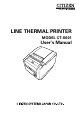
LINE THERMAL PRINTER MODEL CT-S601 User’s Manual
WEEE MARK En If you want to dispose of this product, do not mix it with general household waste. There is a separate collection systems for used electronics products in accordance with legislation under the WEEE Directive (Directive 2002/96/EC) and is effective only within European Union. Ge Wenn Sie dieses Produkt entsorgen wollen, dann tun Sie dies bitte nicht zusammen mit dem Haushaltsmüll.
Declaration of Conformity This printer conforms to the following Standards: The Low Voltage Directive 2006/95/EC, the EMC Directive 2004/108/EC, the RoHS Directive 2002/95/EC, and the WEEE Directive 2002/96/EC. LVD : EN60950-1 EMC: EN55022 EN61000-3-2 EN61000-3-3 EN55024 Class A This declaration applies only to the 230-V model.
GENERAL PRECAUTIONS z Before using this product, be sure to read through this manual. After having read this manual, keep it in a safe, readily accessible place for future reference. z The information contained herein is subject to change without prior notice. z Reproduction or transfer of part or all of this document in any means is prohibited without permission from Citizen Systems.
SAFETY PRECAUTIONS ...WHICH SHOULD BE STRICTLY OBSERVED Before using this product for the first time, carefully read these SAFETY PRECAUTIONS. Improper handling may result in accidents (fire, electric shock or injury). In order to prevent injury to operators, third parties, or damage to property, special warning symbols are used in the User’s Manual to indicate important items to be strictly observed. z After having read this Manual, keep it in a safe, readily accessible place for future reference.
PRECAUTIONS ON PRINTER INSTALLATION WARNING Do not use or store this product in a place where it will be exposed to: * Flames or moist air. * Direct sunlight. * Hot airflow or radiation from a heating device. * Salty air or corrosive gases. * Ill-ventilated atmosphere. * Chemical reactions in a laboratory. * Airborne oil, steel particles, or dust. * Static electricity or strong magnetic fields.
CAUTION Do not use the printer under the following conditions. Avoid locations subject to vibration or instability. Avoid locations where the printer is not level. • The printer may fall and cause an injury. • The quality of printing may deteriorate. Do not obstruct the printer’s air vents. Do not place anything on the printer. Do not cover or wrap the printer in cloth or blankets. • Doing so could cause heat to build up and deform the case or start a fire.
PRECAUTIONS IN HANDLING THE PRINTER WARNING Please observe the following precautions for power source and power cord: Do not plug or unplug the power cord with a wet hand. Use the printer only at the specified supply voltage and frequency. Use only the specified AC adapter with the printer. Check to make sure that the supply outlet from which the printer is powered has a sufficient capacity. Do not supply the printer from a power strip or current tap shared with other appliances.
CAUTION Caution label is attached in the position shown in the following figure. Carefully read the handling precautions before using the printer. THIS LABEL INDICATES THE RISK OF BURNS DUE TO THE HIGH TEMPERATURE OF THE PRINT HEAD AND A RISK OF BEING CUT BY THE MANUAL AND AUTO CUTTERS WHILE THE PAPER COVER IS OPEN. Do not transport this printer with the paper roll inside. • Printer failure or damage may occur. To prevent possible malfunction or failure observe the following.
CAUTION To prevent injury and printer failures from worsening, observe the following: While the paper cover is open, be careful to not touch the manual cutter that is in the paper eject slot. Do not touch the printing surface of the thermal head. Do not touch any of the moving parts (e.g., paper cutter, gears, active electric parts) while the printer is working. In case of trouble do not attempt to repair the printer. Ask Citizen Systems service for repair.
THE TABLE OF CONTENTS 1. GENERAL OUTLINE .................................................................... 9 1.1 1.2 1.3 1.4 Features .......................................................................................... 9 Unpacking .................................................................................... 10 Model Classification .................................................................... 10 Basic Specifications.....................................................................
1. GENERAL OUTLINE The CT-S601 line thermal printer series is designed for use with a broad array of terminal equipment including data, POS, and kitchen terminals. These printers have extensive features so they can be used in a wide range of applications. 1.1 Features z High-speed (200 mm/s) printing. z Design so compact it can be installed anywhere (maximum 3-inch (83-mm) paper roll size) z Choose from two models with either 3-inch (83/80 mm) or 2-inch (60/58 mm) wide paper rolls.
1.2 Unpacking Make sure the following items are included with your printer.
1.4 Basic Specifications Item Model Print method Print width *1 Dot density Print speed Number of print columns *2 Character size*3 Character type User memory Bar code types Line spacing Paper roll Specifications CT-S601 Line thermal dot print method 80 mm/640 dots, 72 mm/576 dots, 64 mm/512 dots, 54.5 mm/436 dots, 54 mm/432 dots, 52.5 mm/420 dots, 48 mm/384 dots, 45 mm/360 dots, 48.75 mm/390 dots, 68.
Notes: *1: When paper width is 83, 80, 60, or 58 mm. *2: The number of printable columns is selected using a memory switch. The number of columns noted in this table refer to typical models. The number of columns varies depending on specifications. *3: Characters appear small because the dimensions include a blank area surrounding each character. *4: The 36AD2 is the AC adapter packaged as an accessory with the CT-S601A. The 36AD3 is the AC adapter built in to the CT-S601S.
z Power switch Press this button to turn the power on or off. z Maintenance cover Not applicable for this product. CAUTION Do not open the maintenance cover. Operation panel POWER LED (green) PAPER LED (orange) ERROR LED (red) FEED button z POWER LED (green) Lights when the power is on, turns off when the power is off. Flashes when data is incoming or a memory error has occurred. z PAPER LED (orange) Lights orange when paper is low (paper near-end) or there is no paper (paper end).
Rear connectors Interface connector (serial, parallel, USB, etc.) Cash drawer kick-out connector Power connector (AC adapter type) AC inlet (built-in power supply type) z Interface connector (serial, parallel, USB, etc.) Connects to the interface cable. The serial interface board is equipped with a DIP switch. z Cash drawer kick-out connector Connects to the cable from the cash drawer. z Power connector (AC adapter type) Connects to the AC adapter cable.
2.2 Inside the paper cover Paper-end sensor (PE sensor) Platen Auto cutter Button to change paper near-end sensor Manual cutter Print head (thermal) Paper thickness selection lever Paper near-end sensor (PNE sensor) z Platen Feeds the paper. z Paper near-end sensor (PNE sensor) Detects when the paper is near the end of the roll. Adjust the position of the sensor to determine when it detects the end of the paper is near.
z Paper thickness selection lever Use this lever to select regular or thick paper according to the thickness of the paper being loaded. CAUTION Do not change the position of the paper thickness selection lever from the factory setting. Refer to 3.8 Setting Paper Thickness 2.3 Other Built-in Functions z Buzzer Buzzes when errors occur or when operations or command operations are performed. Refer to 4.6 Error Messages z User memory You can save user-defined logo and character data in this memory.
3. SETUP 3.1 Connecting the AC Power Cord 1. 2. Turn off the power. z For the built-in power type printer, connect the AC power cord to the AC inlet, and insert the plug into an electric outlet. z For the AC adapter type printer, connect the cable connector of the AC adapter to the power connector. Next, connect the AC power cord to the AC inlet, and insert the plug into an electric outlet.
3.2 Connecting Interface Cables 1. 2. Turn off the power. Orient the interface cable correctly and insert it into the interface connector. Parallel interface Serial interface USB interface (hub type) USB interface Ethernet and Powered USB interfaces are available as options in addition to those listed here. CAUTION Always unplug the AC adapter from the printer before connecting the printer to a Powered USB interface. Failure to do so may damage the host PC.
Use a serial interface cable with the connection layout shown below. 25-pin - 25-pin cable 9-pin - 25-pin cable PC Signal FG Printer Pin 1 Pin 1 PC Printer Signal Signal FG RXD 2 Pin Pin 2 Signal TXD TXD 2 2 TXD TXD 3 3 RXD RXD 3 3 RXD DTR 4 4 RTS CTS 5 4 RTS SG 5 6 DSR DSR 6 6 DSR DSR 6 7 SG SG 7 7 SG CTS 20 DTR DTR 20 20 DTR 8 CAUTION Place the interface cable so people do not trip on it. 3.3 Connecting the Cash Drawer 1. 2. 3. 4. Turn off the power.
(1) Connector pin configuration No. Signal Function 1 FG Frame ground 2 DRAWER1 Cash drawer 1 drive signal 3 DRSW Cash drawer switch input 4 VDR Cash drawer drive power supply 5 DRAWER2 Cash drawer 2 drive signal 6 GND Signal ground (common ground on circuits) Connector used: TM5RJ3-66 (Hirose) or equivalent Applicable connector: TM3P-66P (Hirose) or equivalent (2) Electric characteristics 1) Drive voltage: 24 VDC 2) Drive current: Approx. 1 A max. (not to exceed 510 ms.
3.4 Precautions for Installing the Printer The printer can be used horizontally, vertically, or installed on a wall. However, the CT-S601S (built-in power supply type) cannot be used vertically or installed on a wall. Use the optional stand for vertical applications, and the optional brackets for wall installations. Please refer to the manual for further details. Horizontal position Vertical position Wall installation Change the paper near-end sensor settings for vertical and wall installations.
3.5 Partition for Paper Roll Set the partition to the width of the paper roll you are loading. The partition is set at the factory to the position shown below. z For 3-inch type: 80-mm wide paper roll z For 2-inch type: 58-mm wide paper roll 1. 2. 3. 4. 5. Turn off the power. Press the cover open lever. Open the paper cover. Set the partition in a slot that matches the size of the paper roll you are using. However, to use an 83-mm wide paper roll, remove the partition. Refer to “5.
3.6 Setting the DIP Switch on the Serial Interface Board 1. 2. 3. 4. Turn off the printer and unplug the power cord from the electric outlet. Remove the mounting screws of the serial interface board. Remove the serial interface board from the printer. Set the DIP switch according to the following table. DIP switch Serial interface board mounting screws CAUTION When setting the DIP switch, do not remove any screws except the serial interface board mounting screws.
3.7 Adjusting the Paper Near-end Sensor Change the settings of the paper near-end sensor to set the position at which the near-end of the paper is detected. 1. 2. Use a pointed object, such as a pen, to gently press the button to change the paper near-end sensor. Press and hold down the button while moving the paper near-end sensor up, down, right and left. The sensor positions are shown below for the various diameters of the paper roll used.
3.8 Setting Paper Thickness Set the paper thickness selection lever to the thickness of the paper. (Thick paper can only be used with the label-printing model) To get the best print quality, do not change the factory settings unless printing on thick paper or there is a problem with the print density. Refer to 1.3 Model Classification 1. 2. 3. 4. Turn off the power. Press the cover open lever. Open the paper cover. Set the paper thickness selection lever to A for thick paper or B for regular paper.
3.9 Loading Paper 1. 2. 3. 4. 5. Press the cover open lever while the power is on. Open the paper cover. Load the paper roll so that the printable side of the paper is facing down, as shown by arrow A. Pull a few cm of paper straight out in the direction of arrow B. Close the paper cover in the direction of arrow C until you hear a click. Paper is fed and cut automatically, if the factory settings are set. Refer to 5.
3.10 Attaching the Power Switch Cover Attach this cover to prevent the power switch from being used. 1. Press the power switch cover onto the power switch compartment until it clicks. Power switch cover Put a screwdriver or other pointed object into the grooves on the power switch cover to remove it.
3.11 Attaching the Interface Cover Attach the interface cover to the back of the printer. The shape of the interface cover is different depending on the type of power source. 1. Press the interface cover as shown in the diagram until you hear it click. CT-S601S 3.12 Removing the Interface Cover Press in on both sides at the point indicated by A to remove the interface cover.
4. MAINTENANCE AND TROUBLESHOOTING 4.1 Periodic Cleaning A dirty print head or platen may reduce printing quality or cause malfunctions. Also, if paper dust collects on the sensor’s protective sheet, paper cannot be detected correctly. We recommend cleaning the printer periodically (every 2 to 3 months) as shown below. 1. 2. 3. 4. 5. Turn off the power. Press the cover open lever. Open the paper cover. Wait a few minutes until the print head cools.
4.2 Clearing a Cutter Lock (1) The ERROR LED flashes and the auto cutter blade remains extended because a foreign object or paper jam is obstructing it. If the ERROR LED is flashing, clear the locked cutter as shown below. 1. 2. 3. 4. Press the cover open lever while the power is on. Open the paper cover. Remove any jammed paper including any scraps of paper. (Remove the paper roll that is loaded in the holder also.) Reload the paper roll and close the paper cover.
4.3 Clearing a Cutter Lock (2) The paper cover is designed to be opened if the cutter locks by pressing the cover open lever. If this does not open the paper cover, use the following procedure to clear the locked cutter. 1. 2. 3. 4. 5. 6. 7. 8. 9. Turn off the printer and unplug the power cord from the electric outlet. Press the front cover release button with a pointed object, such as a pen, and open the front cover in the direction of arrow A.
CAUTION Before starting to do maintenance work, be sure to turn off the printer and unplug the power cord from the electric outlet. Be careful not to touch the manual cutter while the front cover is open. Be careful not to touch the opening for the auto cutter while the paper cover is open. The print head is hot immediately after printing. Do not touch it. Do not touch the print head with bare hands or metal objects.
4.5 Hexadecimal Dump Printing Print received data in hexadecimal. If problems such as missing or duplicated data occur, this function allows you to check whether or not the printer is receiving data correctly. How to do hexadecimal dump printing 1. 2. 3. Load paper. While the paper cover is open, press and hold the FEED button while turning the power on, and then close the paper cover. The printer prints “HEX dump print mode” followed by the received data printed in hexadecimal numbers and some characters.
4.6 Error Messages z Paper-end The end of the roll of paper is detected at two stages, paper near-end and paper-end. When paper near-end is detected, the PAPER LED lights. Prepare a new paper roll. When paper end is detected, the PAPER LED and ERROR LED light. Load a new paper roll. z Paper cover open Do not open the paper cover during printing. If the paper cover is opened, the ERROR LED lights or flashes.
The status display for various messages is shown below.
5. OTHER 5.
5.2 Printing Paper Use the paper shown in the following table or paper of the same quality.
5.3 Manual Setting of Memory Switches Memory switches are used to set various printer settings. The memory switches can be set manually (set by hand on the printer) or by commands. This section explains how to perform manual settings. For information on how to set the memory switches using commands, please refer to the Command Reference.
Selected item Manufacturer CITIZEN Paper Character width space Model MSW2-4 Full Col Print MSW3-7 CBM1000 Mode MSW8-1 Print Width MSW6-2 Character Space CBM1000 58 mm — Auto linefeed Valid 432dots — 80 mm — Auto linefeed Valid 576dots — 58 mm — WaitData Invalid 384dots — 80 mm — WaitData Invalid 576dots — CT-S2000 58 mm — Auto linefeed Valid 432dots — 60 mm — Auto linefeed Valid 436dots — 80 mm — Auto linefeed Valid 576dots — 83 mm — Auto linefeed Valid 6
5. Press the FEED button for at least two seconds. A setting for the memory switch is printed, through the cycle, each time the FEED button is pressed for at least two seconds. Press the FEED button for at least two seconds to cycle through the list until the function of the memory switch you want to change is printed. Memory switch function Current setting 6. Press the FEED button. A setting is printed each time the FEED button is pressed in order through the cycle.
The function of each memory switch is shown in the following table. (Shaded values are factory settings.) Switch no.
Switch no. Function OFF ON MSW6-1 Act. For Driver Invalid Valid MSW6-2 Character Space Invalid Valid MSW6-3 Reserved Fixed — MSW6-4 Reserved Fixed — MSW6-5 Reserved Fixed — MSW6-6 Reserved Fixed — MSW6-7 Reserved Fixed — MSW6-8 Reserved Fixed — Switch no.
TZ74916-00F A87667E-0910