Command Reference MOBILE LINE THERMAL PRINTER MODEL CMP-10 Rev. 3.
REVISION Rev. No. Rev. 1.00 Date 2002/11/15 Newly issued Comment Rev. 1.01 2002/12/18 Revised P. 1, P. 2, P. 47, P. 54, P. 56, P. 59 Rev. 1.02 2003/01/17 Added Chapter 3 (Character Codes Table) and Chapter 4 Rev. 2.00 2003/06/30 Added ESC >, ESC l, FF (Firmware Ver. 1.95) Revised GS ) Added Chapter 5 to Chapter 10 Rev. 3.00 2006/07/13 Added baud rate 38400 at page of ESC S n and 5.1 (2) Added GS z Rev. 3.01 2006/08/31 Revised range of CODE128 on Page56 Rev. 3.
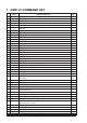
1. CMP-10 COMMAND SET 1 2 3 4 5 6 7 8 9 10 11 12 13 14 15 16 17 18 19 20 21 22 23 24 25 26 27 28 29 30 31 32 33 34 35 36 37 38 39 40 41 42 43 Code BEL HT LF CR ESC RS ESC SP ESC ! ESC $ ESC % ESC & ESC * ESC + ESC – ESC .
4 45 46 47 48 49 50 51 52 53 54 55 Code GS H GS L GS W GS ^ GS a GS f GS h GS k GS w GS z ESC l FF Command Function Selecting of Printing Position of HRI Code Setting the left margin Setting the print area width Executing the Macro Enabling/Disabling ASB (Automatic Status Back) Selecting the font of HRI characters Selecting the height of the Bar Code Printing the bar code Selecting the horizontal size (Scale factor) of the Bar Code Saving AT command sequences to send to Bluetooth module Specify/canceling
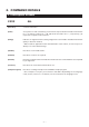
2. COMMAND DETAILS 2.1 Description of Items XXXX ALL [Function] Command Function [Code] A sequence of code constituting a command is represented in hexadecimal number for < >H, binary number for < >B, and decimal number for < >, respectively; [ ]k represents a repeat count of k-times. [Range] Indicates an argument value (setting range) for the command in hexadecimal number (partly in decimal number). * When used for application other than defined in each control, an error may occur.
BEL [Function] Sounds the Buzzer [Code] <07>H [Outline] By executing this command the buzzer will beep. This command functions in the same manner as ESC RS.
HT [Function] Horizontal Tab Command [Code] <09>H [Outline] Shifts the printing position to the next horizontal tab position. • Ignored when the next horizontal tab position has not been set. [Caution] • The horizontal tab position is set by ESC D. • Initial setting of the horizontal tab position is each 8 characters in 9th, 17th, 25th, columns from FONT A.
LF [Function] Printing and Paper Feed Command [Code] <0A>H [Outline] Prints data inside the input buffer and feeds lines based on the line feed amount having been set. • The head of the line becomes the next print starting position.
CR [Function] Print one line Command [Code ] <0D>H [Outline] This command is ignored or its action is the same as LF depending on the last execution of GS ) 2 command (FLAG SETTING COMMAND). If Flag 2 is 0, carriage return (CR) command is ignored. If Flag 2 is 1, CR comamnd will act as LF command. [Default] CR command is ignored. If you want that it acts like LF command set flag 2 to 1 by GS ) command.
ESC SP n [Function] Setting the right space amount of the character [Code] <1B>H<20>H [Range] {0 =< n =< 20(Hex)} [Outline] The rightward space amount is set in dot unit (1/203 inch unit). [Caution] The rightward space amount in doublewide mode is made double of the set volume.
ESC ! n [Function] Collective Specifying Printing Mode [Code] <1B>H<21>H [Range] {0 =< n =< FF(Hex)} [Outline] Printing mode is assigned.
[Sample Program] PRINT #1, CHR$(&H1B) + “!” + CHR$(&H00) + “H” ; PRINT #1, CHR$(&H1B) + “!” + CHR$(&H01) + “H” ; PRINT #1, CHR$(&H1B) + “!” + CHR$(&H08) + “H” ; PRINT #1, CHR$(&H1B) + “!” + CHR$(&H10) + “H” ; PRINT #1, CHR$(&H1B) + “!” + CHR$(&H20) + “H” ; PRINT #1, CHR$(&H1B) + “!” + CHR$(&HB9) + “H” ; PRINT #1, CHR$(&HA) ; END [Print Results] Font A Font B Font A + Emphasis > > > > > > > Font B + Emphasis + Quadruple + Underline Font + Underline Font A + Double Width Font A + Double Height — 10 —
ESC $ n1 n2 [Function] Specifying the Absolute Positions [Code] <1B>H<24>H [Range] {0 =< n1 =< FF(Hex)} {0 =< n2 =< 1(Hex)} [Outline] The printing start position is specified in the number of dots (1/203 inch unit) from the beginning of line. • The number of dots is divided by 256, whose quotient is taken as n2 and the residual as n1. • Therefore, the printing start position is equal to n1 + n2 × 256 from the beginning of line. [Caution] Specifying beyond the line end is ignored.
ESC % n [Function] Specifying/Canceling Download Character Set [Code] <1B>H<25>H [Range] {0 =< n =< FF(Hex)} [Outline] Specifying/canceling download characters. Further, only the lowest bit (n0) is valid for n. n (Hex) 0 1 Function Selecting download character set Canceling download character set [Caution] This setting cannot be restored to initial value even with Initialize command or by turning power OFF.
ESC & m n1 n2 [d] k [Function] Define user characters [Code] <1B>H<26>H[]k [Range] {m = 0, 1, 2, 3(Hex)} {20 =< n1 =< FF(Hex)} {n1 =< n2 =< FF(Hex)} {k=(n2-n1+1)*48} (m=2) {k=(n2-n1+1)*16} (m=3) [Outline] Defines a group of user characters.
ESC * m n1 n2 [d] k [Function] Specifying the Bit Image Mode [Code] <1B>H<2A>H [d] k [Range] {m= 0, 1, 20, 21(Hex)} {0 =< n1 =< FF(Hex)} {0 =< n2 =< 1(Hex)} {0 =< d =< FF(Hex)} {k = n1 + FF(Hex) x n2} (m=0, 1(Hex)) Number of bytes containing image data {k = (n1 + FF(Hex) x n2) x 3} (m=20, 21(Hex)) Number of bytes containing image data [Outline] According to the number of dots specified in n1, n2, specify the bit image of mode m. • The No.
[Sample Program] PRINT #1, CHR$(&H1B) + “ * ”; PRINT #1, CHR$(0) + CHR$(20) + CHR$(0); GOSUB IMG1 PRINT #1, CHR$(&HA); PRINT #1, CHR$(&H1B + “ * ”; PRINT #1, CHR$(1) + CHR$(20) + CHR$(0); GOSUB IMG1 PRINT #1, CHR$(&HA); PRINT #1, CHR$(&H1B) + “ * ”; PRINT #1, CHR$(32) + CHR$(20) + CHR$(0); GOSUB IMG2 PRINT #1, CHR$(&HA); PRINT #1, CHR$(&H1B) + “ * ”; PRINT #1, CHR$(33) + CHR$(20) + CHR$(0); GOSUB IMG2 PRINT #1, CHR$(&HA); END [Print Results] ← 8-dot single density ← 8-dot double density ← 24-dot
This command has one more version. [Function] Specifying the Bit Image Mode (PCX format) [Code] <1B>H<2A>H{<00>H} [d]k [Range] {m= 10, 11 or 12(Hex)} {0 =< n =< 30(Hex)} {0 =< a =< 18(Hex)} {0 =< d =< FF(Hex)} {0 =< k =< n x 18(Hex)} [Outline] Designates a bit image of n*8 dots horizontal by 24 or a dots vertical. Dot density is fixed at 203 dpi both horizontally and vertically. Bit image mode selected by the value of m is shown in the following table.
ESC + [Function] Switch OFF the printer [Code] <1B>H<2B>H [Range] None [Outline] This command is used for switching off the printer from the host. Sending this command causes the same operation as that by setting the power switch to off. ESC – n [Function] Specifying/ Canceling Underline [Code] <1B>H<2D>H [Range] {0 =< n =< 02(Hex)} [Outline] Specifying/canceling an underline. • Types of underlines by n value are shown below: n (Hex) 0 1 2 Type Canceling an underline.
ESC . [Function] Printer self test [Code] <1B>H<2E>H [Range] None [Outline] Prints test page, downloaded bit image, and self-diagnostic information. The selfdiagnostic information includes print density, print head temperature, battery voltage, Serial or IrDA interface, baud rate, and memory switch setting. [See Also] ESC T ESC 2 [Function] Specifying 1/6-inch line feed rate [Code] <1B>H<32>H [Outline] The line feed rate per line is specified by 1/6 inch.
ESC 3 n [Function] Setting line feed rate of minimum pitch [Code] <1B>H<33>H [Range] {0 =< n =< FF(Hex)} [Outline] The line feed rate per line is specified by n/203 inch. [Default] n = 22(Hex) 1/6-inch [Sample Program] See Sample Program and Print Results for ESC 2.
ESC = n [Function] Data Input Control [Code] <1B>H<3D>H [Range] {0 =< n =< FF(Hex)} [Outline] Selecting equipment in which data input from the host is effective. • Each bit of n indicates as follows: Bit Equipment 0 1 2 3 4 5 6 7 Printer Not defined Not defined Not defined Not defined Not defined Not defined Not defined Value 0 Invalid 1 Valid • When the printer has not been selected, this printer abandons all the received data until it is selected by this command.
ESC > n [Function] Saving current setting [Code] <1B>H<3E>H [Range] n = 0 or 1 [Outline] This command saves International character, Serial port baud rate, Print density, Auto power off time and maximum speed at Infrared communication to NV memory so that the setting can be resumed automatically when power on after setting data on RAM memory is gone by like battery is disconnected. n (Hex) 0 1 Type Max speed at Infrared communication is 115200 bps.
ESC ? n [Function] Reading magnetic stripe reader [Code] <1B>H<3F>H [Range] {0 =< n =< 7(Hex)} [Outline] When the command is received the bicolor LED is shining in RED and the printer is waiting for the magnetic card to be swiped through the reader. If even after 10 seconds the card is not swiped the command is aborted automatically. Printer returns the information read from the tracks followed by 00(Hex). Reads the data of the track in the following table by the value of n.
ESC @ [Function] Initializing the Printer [Code] <1B>H<40>H [Outline] Clears data stored in the print buffer and brings various settings to the initial state (Default state). Items not cleared are as shown below. • Data inside the internal input buffer are not cleared. • Does not clear any data in the internal input buffer. • Does not clear downloaded characters. • Does not clear defined downloaded characters. • Does not clear defined downloaded bit image. • Does not clear defined macro.
ESC D [ n ] k NUL [Function] Setting Horizontal Tab Position [Code] <1B>H<44>H [ ] k<00>H [Range] {0 =< n =< FF(Hex)} {0 =< k =< 20(Hex)} [Outline] Specifying a horizontal tab position. • “n” indicates the no. of columns from the beginning to the horizontal tab position. At this time, n= set position – 1 is to be specified. For example, to set the position at 9th column, n=8 is to be specified. • k denotes the number of horizontal tab positions you want to set.
ESC E n [Function] Specifying/canceling highlighting [Code] <1B>H<45>H [Range] {0 =< n =< FF(Hex)} [Outline] Specifying/canceling the highlighting characters. • “n” is valid only for the lowest bit (n0). n (Hex) 0 1 Type Canceling highlighting. Specifying highlighting. • This is effective only for font A (12 × 24 dots) • Dot configuration of a highlighted character includes one extra dot added at its side.
ESC G n [Function] Specifying/canceling Double Printing [Code] <1B>H<47>H [Range] {0 =< n =< FF(Hex)} [Outline] Specifying/canceling the double printing. • “n” is valid only for the lowest bit (n0). • Control by n is shown as follows. n (Hex) 0 1 Type Canceling double printing. Specifying double printing. • This is effective to font A (12 × 24 dots) [Caution] • The print result of Double printing and highlight character printing is completely same.
ESC J n [Function] Printing and feeding paper n/203 inch [Code] <1B>H<4A>H [Range] {0 =< n =< FF(Hex)} [Outline] Prints data in the print buffer and feeds paper by n/203 inch. • This function is temporary and does not affect the feed operation thereafter. • The beginning of the line is to be considered as the next printing start position. [Default] Initial value is not defined. [Sample Program] See Sample Program and Print Results for ESC 2 on Page 18.
ESC S n [Function] Setting serial interface communication speed [Code] <1B>H<53>H [Range] {0 =< n =< 6(Hex)} {30 =< n =< 36(Hex)} n (Hex) 0, 30 1, 31 2, 32 3, 33 4, 34 5, 35 6, 36 7, 37 Speed (bps) 1200 2400 4800 9600 19200 57600 115200 38400 (Firmware 2.04 or later) [Outline] Sets the communication speed for the serial interface. The command is valid only when the printer is connected through a serial cable. It is not valid when using IrDA interface.
ESC V n [Function] Specifying/Canceling 90°-right- turned Characters [Code] <1B>H<56>H [Range] {0 =< n =< 1(Hex)} [Outline] Specifying/canceling characters 90°-right- turned character. “n” means the followings. n (Hex) 0 1 Condition Canceling 90°-right- turned Characters Specifying 90°-right- turned Characters [Caution] No underlines are attached to 90°-right- turned characters. [Default] The initial value of n is “0”.
ESC Y n [Function] Specifying print density [Code] <1B>H<59>H [Range] {0 =< n =< 5(Hex)} [Outline] Specifies the print density. “n” means the followings. n (Hex) 0 1 2 3 4 5 Condition 70 % density 80 % density 90 % density 100 % density 120 % density 150 % density [Caution] Higher density may lead to slower printing. Increasing the density allows Low battery to be detected easily.
ESC Z [Function] Returning diagnostic information [Code] <1B>H<5A>H [Outline] The printer will return 32 bytes of information with the following structure: 1-22: Printer name up to 22 charachters. 23-25: Firmware version 26-27: Language version, described by two characters. 28-32: When the corresponding bit is 1, the function is supported and when 0, the function is not supported.
BYTE 29 BIT7 BIT6 BIT5 BIT4 BIT3 BIT2 BIT1 BIT0 Update via firmware interface Not in use Not in use Not in use Not in use Not in use Not in use Reserved, always 1 BYTE 30 BIT7 BIT6 BIT5 BIT4 BIT3 BIT2 BIT1 BIT0 Not in use Not in use Not in use Not in use Not in use Not in use Not in use Reserved, always 1 — 32 —
BYTE 31 BIT7 BIT6 BIT5 BIT4 BIT3 BIT2 BIT1 BIT0 Not in use Not in use Not in use Not in use Not in use Not in use Not in use Reserved, always 1 BYTE 32 BIT7 BIT6 BIT5 BIT4 BIT3 BIT2 BIT1 BIT0 Not in use Not in use Not in use Not in use Not in use Not in use Not in use Reserved, always 1 — 33 —
ESC \ n1 n2 [Function] Specifying the relative positions [Code] <1B>H<5C>H [Range] {0 =< n1 =< 255} {0 =< n2 =< 255} [Outline] The printing start position is specified in the number of dots (1/203 inch unit) from the current position. • Rightward direction is taken as plus and leftward direction as minus. • To specify N dot in minus (left) direction, use a complement of N for assignment.
ESC ` [Function] Returning the battery voltage and Printer Head temperature [Code] <1B>H<60>H [Outline] When this command is send to CMP-10, the printer will return the current value of battery voltage and the current temperature of the printer thermal head. • Battery voltage is returned in the format: battery voltage × 10 + 20H and head temperature is returned in the format: head temperature + 20H. [Sample Program] PRINT #1, CHR$ (&H1B) + “ ` ”; [Print Results] Suppose the battery voltage is 7.
ESC a n [Function] Aligning the characters [Code] <1B>H<61>H [Range] {0 =< n =< 2(Hex)} [Outline] All the printed data within one line are aligned in the specified position. Depending on n value, positional alignment is carried out as in the table below: n (Hex) 0 1 2 [Caution] Position Left end alignment Centering Right end alignment • This is valid only when n is inputted at the beginning of line. • The initial value of n is “0”.
ESC c5 n [Function] Enabling/Disabling Panel Switches [Code] <1B>H<63>H<35>H [Range] {0 =< n =< FF(Hex)} [Outline] Selecting the LF switch valid/invalid. • “n” is valid only in the lowest bit (n0). n (Hex) 0 1 Condition LFSW valid. LFSW invalid. [Caution] • When the panel switch is disabled with this command, the LF switch is disabled. Therefore, the paper cannot be fed by operating the LF switch.
ESC d n [Function] Printing and Feeding the paper by n lines [Code] <1B>H<64>H [Range] {0 =< n =< FF(Hex)} [Outline] Prints data inside the buffer and feeds paper by n lines. Specified line does not remain. The beginning of the line is to be considered as the next printing start position. [Default] The initial value is not defined.
ESC v [Function] Transmitting the printer status [Code] <1B>H<76>H [Outline] Current printer status is transmitted. Status sent out consists of 1 byte whose content is as in the table below. Bit [Caution] Function 0 1 2 Not defined Not defined Paper or paper cover 3 4 5 6 7 Not defined Not used Not defined Not defined Not defined Value 0 1 With paper and cover closed No paper or cover open Fixed to 0 – In paper end status, this command may be unreceptible state due to BUSY state.
ESC x n [Function] Selecting the time interval for automatically switching Off the printer. [Code] <1B>H<78>H [Range] {1 =< n =< 3C(Hex)} [Outline] Sets the time interval after which the printer will be switched Off automatically if there is no incoming data through the Serial interface, there is no IrDA communication and LF button is not pressed. The maximum value for the interval is 60 minutes <3C>H .
ESC { n [Function] Specifying/Canceling the Inverted Characters [Code] <1B>H<7B>H [Range] {0 =< n =< FF(Hex)} [Outline] Specifying/canceling inverted characters. • “n” is valid only for the lowest bit (n0). n (Hex) 0 1 Condition Canceling inverted characters. Specifying inverted characters. [Caution] • Inverted-printing means printing the line at 180° turned. • This is valid only when this is specified at the beginning of a line. [Default] • The initial value of n is “0”.
GS ) n m [Function] Setting of printer flags [Code] <1D>H<29>H [Range] {0 =< n =< 8(Hex)} {m = 0 or 1(Hex)} [Outline] This model has 8 memory switches and selecting, releasing, and changing a function is available with this command. Memory switch setting is retained even after printer power off. n specifies the number of memory switch to be operated. m specifies a selection. The contents of individual memory switches are as shown below.
GS * n1 n2 [ d ] n1 n2 D1 ...... Dn [Function] Defining the Download Bit Image (LOGO) [Code] <1D>H<2A>H [ < d > ] [Range] {1 =< n1 =< 7F} Defines horizontal size of downloaded image. {1 =< n2 =< F8} Defines the vertical size of downloaded image. [Outline] Defines downloading bit images of the number of dots specified by n1 and n2. The numbers of dots are n1 × 8 in horizontal direction and n2 × 8 in vertical direction.
[Print Results] GS / m [Function] Printing the Download, Bit Image [Code] <1D>H<2F>H [Range] {0 =< m =< 03(Hex)} [Outline] Prints download bit image in a mode specified by m. • Modes can be selected by m are shown below.
GS : [Function] Starting/Ending Macro Definition [Code] <1D>H<3A>H [Outline] Specifying starting/ending macro definition. Means termination when received while defining a macro. [Caution] • Maximum content available for macro definition is 3328 bytes. • A portion exceeding 3328 bytes is not defined. • Even with ESC @ (initialization of the printer) having been executed, defined content is not cleared. Therefore, it is possible to include ESC @ into the content of macro definition.
GS H n [Function] Selecting of Printing Position of HRI Code [Code] <1D>H<48>H [Range] {0 =< n =< 3(Hex)} [Outline] Selecting printing position of HRI code in printing bar codes. • “n” means the followings. n (Hex) 0 1 2 3 Printing Position No printing Above the bar code Below the bar code Both above and below the bar code The HRI code refers to the bar code-turned characters so that you can read them. [Caution] The HRI code is printed in the font selected with GS f.
GS L nL nH [Function] Setting the left margin [Code] <1D>H<4C>H [Range] {0 =< nL =< FF(Hex)} {0 =< nH =< FF(Hex)} [Outline] This command sets the left margin specified by nL and nH. The value of the left margin is [(nL + nH × 256) × 1/203] inches. [Caution] • This command only works when it is entered at the beginning of a line. • The maximum settable left margin is equal to the horizontal printable area. A setting greater than this maximum is trimmed to the maximum.
GS W n [Function] Setting the print area width [Code] <1D>H<57>H [Range] {0 =< nL =< FF(Hex)} {0 =< nH =< FF(Hex)} [Outline] Sets the print area width specified by nL and nH. • The print area width will be [(nL + nH × 256) × 1/203] inches. Printable Area Left Margin [Caution] Printable Area With • This command only works when it is entered at the beginning of a line.
(3) When sufficient area cannot be secured even by executing the processing (2), the right space is decreased. • When bit image (or downloaded bit image) is developed, if the print area width is less than the minimum lateral width of the bit image (2 dots for single density, 1 dot for double density), the following processing is carried out only in the same line.
GS ^ n1 n2 n3 [Function] Executing the Macro [Code] <1D>H<5E>H [Range] {0 =< n1 =< FF(Hex)} {0 =< n2 =< FF(Hex)} {0 =< n3 =< 1(Hex)} [Outline] Executing contents defined in macro. The following items are set for parameters n1 to n3. n1: The number of times of macro execution n2: Waiting time on macro execution. Waiting time of n2 × 100 msec is given for every execution.
GS a n [Function] Enabling/Disabling ASB (Automatic Status Back) [Code] <1D>H<61>H [Range] {0 =< n=< FF(Hex)} [Outline] This command selects the status item to be addressed by ASB (Automatic Status Back.
BYTE 2 BIT7 BIT6 BIT5 BIT4 BIT3 BIT2 BIT1 BIT0 Not in use (0) Not in use (0) Not in use (0) Not in use (1) Not in use (0) Not in use (0) Thermal head is overheated (1) Not in use (0) BYTE 3 BIT7 BIT6 BIT5 BIT4 BIT3 BIT2 BIT1 BIT0 Not in use (0) Not in use (1) No paper or cover open (1) No paper or cover open (1) Not in use (0) Not in use (0) Not in use (0) Not in use (0) — 52 —
BYTE 4 BIT7 BIT6 BIT5 BIT4 BIT3 BIT2 BIT1 BIT0 Not in use (0) Not in use (0) Not in use (0) Not in use (0) Not in use (1) Not in use (0) Not in use (0) Not in use (0) [Caution] • If any status item is enabled, the status is sent to the host when this command is executed. After that time on, the status is sent each time an enabled status item changes. Because each status item represents the current condition, status items disabled for ASB may also have changed.
GS f n [Function] Selecting the font of HRI characters [Code] <1D>H<66>H [Range] {n = 0, 1(Hex)} [Outline] Selecting the font of HRI characters in printing bar code. The type of font can be selected with “n” as follows: n (Hex) 0 1 Font Font A (12 × 24) Font B (9 × 16) The HRI characters refer to the bar code-turned characters so that you can read them. [Caution] The HRI characters are printed at the position specified with GS H.
GS h n [Function] Selecting the height of the Bar Code [Code] <1D>H<68>H [Range] {1 =< n =< FF(Hex)} [Outline] Selecting bar code height. n denotes the number of dots in the vertical direction. [Default] n = A2(Hex) 162 dots [Sample Program] See Sample Program and Print Results for GS w .
GS k m [d1 ..... dk] NUL GS k m n [d1 ...... dn] [Function] Printing the bar code [Code] (1) <1D>H<6B>H [d1.....dk] NUL (2) <1D>H<6B>H [d1....dn] [Range] (1) 0 =< m =< 6 The definitions of “k” and “d” vary with the bar code system. (2) 65 =< m =< 73 The definitions of “n” and “d” vary with the bar code system. [Outline] Selects a bar code system and prints the bar code.
[Caution] For (1): • This command ends with a NUL code. • For UPC-A or UPC-E, the bar code is printed when 12 bytes of bar code data have been entered, and the subsequent data is handled as normal data. • For JAN13, the bar code is printed when 13 bytes of bar code data have been entered, and the subsequent data is handled as normal data. • For JAN8, the bar code is printed when 8 bytes of bar code data have been entered, and the subsequent data is handled as normal data.
JAN-8(EAN) This bar code, consisting of numerals only, has a fixed length of 8 columns; a 7column number entered from the host or application software plus a check digit (8th column) automatically calculated inside the printer. If the 8th-column numeral is sent from the host, the entire bar code will be printed as it is. CODE39 This bar code, consisting of upper-case alphabetic characters and numerals, has a variable length of columns. The start/stop code “*” is automatically added by the printer.
When sending print data, note these points: (1) Each string of bar code data must begin with a code set select character (CODE A, CODE B, or CODE C), which selects the first code set to use. (2) Every special character is specified by a combination of two characters: a brace “{“ followed by one character. A brace “{“ itself is sent twice consecutively. SPECIAL CHARACTERS: Hex.
[Descriptionof Bar Codes] UPC-A, UPC-E, JAN-13 (EAN), JAN-8 (EAN), CODE39, ITF, CODABAR, CODE128 Type UPC-A Outline of Symbol 12-column fixed-length bar code consisting of numerals only. Max. Column — 8-column fixed-length bar code consisting of numerals only. Abbreviated version of UPC-A. — JAN-13 13-column fixed-length bar code consisting of numerals only. — JAN-8 8-column fixed-length bar code consisting of numerals only. — CODE39 Variable-length bar code consisting of alphabets and numerals.
GS w nL nH [Function] Selecting the horizontal size (Scale factor) of the Bar Code [Code] <1D>H<77>H [Range] {2 =< n =< 4(Hex)} [Outline] Selecting bar code width. n denotes the number of dots in fine element width. [Default] The initial value of this width is “3”.
GS z ..... ^C (Available only with firmware version 2.12 or later) [Function] Saving AT command sequences to send to Bluetooth module [Code] <1D>h <7A>h [d1….dn] <03>h [Range] 0 =< n =< 60 [Outline] Printer saves the AT command sequences specified by [d1….dn] in the NV memory. At the first time of power-on after saving the sequences, printer transfers the sequences to Bluetooth module. Then the printer clears the sequence from NV memory and the printer power is turned off.
[Example] To enable the pairing information to be preserved, following command sequences need to be sent to the printer. GS z AT*PAIRINFO=1 CR ^C <1D 7A 41 54 2A 50 41 49 52 49 4E 46 4F 3D 31 0D 03>h Printer power is turned off by receiving this command. Print result at power on after receiving this command as follows.
BLACK MARK FUNCTION ESC l n [Function] Specify/canceling black mark function [Code] <1B>H<6C>H [Range] n = 0 or 1 [Outline] Specifying / canceling the black mark function. n (Hex) 0 1 Type Canceling black mark function Specifying black mark function [Caution] Black mark function uses PE sensor of CMP-10 for black mark sensor. Therefore, the condition of detecting paper end and detecting open cover is changed in this mode.
Note for Black Mark Function 1. Error detection at black mark mode Paper end is checked during printing but black mark is not checked. After receiving FF command, printer checks black mark and paper end. Once black is detected and white is detected again within 6 mm paper feed, it is determined as black mark. If the white is not detected within 6 mm paper feed, it is determined as paper end.
3.
4. Setup menu function (After Ver2.20) Make sure the printer power is off. Press ON/OFF switch and keep pressed for about 5 seconds until .LED is changed to red and leave the switch. Then buzzer beeps and printer prints current setting and goes to setup menu as follows.
D. CHANGE BAUD RATE ? If you want to change the baud rate of serial communication, choose YES here and if not, choose NO and go to next items. If you choose YES, baud rate choice such as “1200 bps ?” are shown continuously. If the baud rate is right one, choose YES and if not, choose NO. When YES is chosen, printer prints next menu items. The choice of baud rate are 1200, 2400, 4800, 9600, 19200, 38400, 57600, 115200 bps. The default setting is 9600 bps. E.
The list of choice in the setup menu Top question items Additional questions (Bold items is default value.
YES = ON/OFF SWITCH NO = LF SWITCH Hold ON/OFF till LED changes to red. Current settings are printed.
5. PROGRAMMING CONSIDERATIONS 5.1 Notes at Lowered Battery Voltage When battery is low, highly loaded printing such as printing of graphics with much black area may cause power off during printing. When executing high loaded printing, charging the battery before lowing of battery voltage is recommended while keeping checking the information on the battery by the use of relevant command. 5.
6. SERIAL INTERFACE 6.
6.3 Explanation of Input/Output Signals (1) RXD This is signal, receiving data from the host. On occurrence of framing error, overrun error, or parity error, the data is printed as “?”. (2) TXD This signal is for data flow control by X-ON/X-OFF. If data remains in the printer’s input buffer is 2048 bytes or less, the printer transfers a DC3 (13H: Data Receive Not Ready) signal to the host.
6.
7. INFRARED COMMUNICATION SPECIFICATIONS 7.1 Basic Specification (1) Interface: Infrared transceiver mode (2) Data transfer system Half duplex Asynchronous (3) Baud rate: 9600, 19200, 38400, 57600, 115200 bps (Max baud rate can be set at 57600 bps by command.
8. MECHANICAL SPECIFICATION 8.1 Printer Mechanism (1) Print method Line thermal printing (2) Number of dot 384 dot/line (3) Head density 8 dot/mm (4) Print width 48 mm (5) Sensors Head temperature Paper end Head-up Thermistor Photo Interrupter Mechanical switch (6) Paper Paper width Paper thickness Recommended paper Outside diameter 58 mm+0/–1 65 µm TF50KS-E2D (Nippon Paper) Max 40 mm or 50 mm (by model) (7) Paper feed force 0.49N or more (8) Paper keep force 0.
9. POWER RELATED SPECIFICATIONS 9.1 Battery (1) Battery type Lithium-ion battery pack (2) Maximum capacity 2000 mAh (3) Number of sells 2 (4) Maximum output voltage 4.2V/Cell (5) Cut-off voltage 2.75V/Cell (6) Standard charge 1000 mA, 23ºC, 4.
10. AC ADAPTOR (1) Input voltage 100V ~ 240V AC (50/60 Hz) (2) Input current 250 mA (3) Rated output 9V ±5% (4) Efficiency 65% or more (AC 100V/50 Hz full load) 70% or more (AC 240V/50 Hz full load) (5) Ripple and noise voltage Less than 150 mVp-p (9 VDC) (6) Insulation test More than 100M ohm (DC 500V, 1 minute, between primary and secondary circuit and chassis) (7) Leakage current 0.