Handy Printer PD-24 User's Manual
Latest Information Printer Drivers, Servicing and Consumables For the latest information on your PD-24 printer: • where to obtain service inside or outside of the warranty period • printer drivers for the latest operating systems • additional consumables and accessories please contact Citizen’s office in your region: United States, Canada, South America: 363 Van Ness Way, Suite 404 Torrance, CA 90501. USA Tel: (310) 781-1460 http://www.citizen-systems.
Contents FCC Declaration of Conformity ..................................................... 4 DECLARATION OF CONFORMITY ................................................ 5 Compliance Statements ................................................................ 6 Safety Instructions ........................................................................ 7 1. Confirming the Accessories ..................................................... 13 Included Accessories ................................................
FCC Declaration of Conformity We, the Responsible Party: declares that the product: Trade Name: Product Name: Model Number: Citizen Systems America Corporation 363 Van Ness Way, Suite 404 Torrance, CA 90501. USA Tel: (310) 781-1460 CITIZEN Printer PD-24 confirms to the following specifications: Regulation: FCC Part 15B, Class B Test Method: ANSI C63.4-2003 and therefore is in compliance with the protection requirement of FCC Rules relating to electromagnetic compatibility.
DECLARATION OF CONFORMITY We, Citizen Systems Europe GmbH Park House 643-651 Staines Road Feltham, Middlesex TW14 8PA. United Kingdom declare under our sole responsibility that the product: Product Type: Thermal Printer Model Name: PD-24 manufactured by : Crown Young Industries Ltd Block 10, Tong Fu Yu Industrial Zone Long Tian Residents Committee Keng Zi Subdistrict Office, Long Gang District Shen zhen 518122, P.R.
Compliance Statements FCC Compliance Statement for American Users This equipment has been tested and found to comply with the limits for a Class B digital device, pursuant to Part 15 of the FCC Rules. These limits are designed to provide reasonable protection against harmful interference in a residential installation.
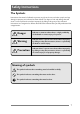
Safety Instructions The Symbols Instructions that must be followed to prevent any risk to the user and other people and any damage to property are indicated as shown below. The degree of risk and damage that will occur if a user operates the machine improperly by failing to obey any of the indicated instructions are categorized as follows. Read the User’s Manual after you fully understand this categorization.
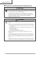
Safety Instructions 7 Precautions to be followed when handling the printer Warning • Do not use the printer if it becomes hot, produces smoke or a strange smell, etc. as it could start a fire. Immediately switch off the printer and remove both the AC adaptor and/or battery pack, if installed. • If any foreign (metal scraps, water, or other fluid) gets inside the printer, immediately switch off the printer and remove both the AC adaptor and/or battery pack, if installed.
7 Precautions to be followed when operating the printer Warning • Be extremely careful not to touch the print head or serrated tear bar when replacing the paper. After printing, the print head can become hot and there is a danger of it burning your hand. Also, care should be taken when handling the cutter as it might cut your hand. Precaution • If you use any paper other than the designated kind, the print quality will fall and the service life of the print head (printing unit) will be reduced.
Safety Instructions 7 Precautions when using the battery pack Danger • Do not use any battery pack other than the specified type. Using a type other than the specified type may cause an explosion. • Use only the specialized charger. • Do not take it apart or modify it. • Do not short circuit the terminals. • Do not use, charge, or leave the battery pack near fire, out in the hot sun, or in any other hot place. • Do not place it in a fire. • Do not hit or drop the battery pack.
7 Precautions when using the charger (optional) Precaution • Do not modify the charger nor remove its cabinet. • Do not damage or modify the power cord. This may cause a short circuit or accident. • Do not drop the charger or apply a strong shock to it. • Use a household AC100-240V power source. • Be very careful to keep water, metal etc. out of the inside of the battery pack. • Do not use it in the following places.
Safety Instructions 7 Precautions when using thermal paper (printing paper) Precaution When using thermal printing paper, take the following precautions. Thermal printing paper becomes discolored or degenerates, resulting in faint printing. • Do not put printed paper in bright light for a long period. • Avoid high temperature, humidity, fluids, and sunlight. • Do not use glue, adhesive, or adhesive tape containing a volatile organic solvent to retain printed thermal paper by applying it to ground paper.
Confirming the Accessories Included Accessories After opening the package, confirm that the printer and the following standard accessories have been included. & AC adaptor (PD79910-0S) & Sample Roll Paper & Battery pack (PD69910-2S) 1 & User's Manual (This Volume) Optional Accessories The following optional accessories are available for use with this printer. Purchase as needed.
Before use External Appearance and Part Descriptions Front view of the printer 9 2 = 1 0 = 5 7 LED (page 16) 4 6 5 8 3 1 FEED Button (paper feed) If it is pressed once, it feeds one line. If it is held down, it feeds approximately 300 mm (1 feet) then stops. But even if it is continuously held down, it feeds a specified length of paper then stops. It will not feed if there is no paper. 2 MENU Button It is used to set the menu.
External Appearance and Part Descriptions 3 Serial Interface To receive data serially, connect the specialized RS-232C cable (option). 4 USB Interface To receive data from the USB interface, connect the specialized USB cable (option). 5 Strap Holder 1 6 Optical Receiver Receives data transmitted by infrared transmission. (see page 29). 7 AC Adaptor Terminal Cover This cover is used to protect the AC Adaptor terminal. Be sure to always close the cover when not using the AC adaptor.
Before use LED panel 1 POWER LED 2 STATUS LED 3 ERROR LED Functions of the LED Each LED is illuminated continuously or flashing according to the status of the printer. The POWER LED and the STATUS LED emit either green, orange, or yellow, and the ERROR LED emits red in combinations that indicate the status of the printer. (See the following page.
External Appearance and Part Descriptions LED Indicator Table Printer Status Printing standby status (ONLINE) During Bluetooth link During data reception (all interfaces) No paper (it has run out) Roll paper cover open Head overheated Motor overheated POWER LED STATUS LED ERROR LED (green, orange, yellow) (green, orange, yellow) Steady green Steady green Steady green Steady green Steady green Steady green Steady green Low battery Not on (red) Not on Not on (green) Not on 1 (orange) Not on Not o
Before use External Appearance and Part Descriptions Inside the Printer 1 2 3 2 3 4 5 1 Paper Feed Roller This feeds the paper to the paper exit slot. 2 Paper Holder The roll paper is placed here. 3 Cover Open Sensor Switch Detects whether the roll paper cover is open or closed. 4 Paper End/Black Mark Detection Sensor Detects whether or not paper is loaded. 7 About the Black Mark This is a black sensing mark that is pre-printed on the paper’s print side.
External Appearance and Part Descriptions Back of Printer 3 1 Power Switch Slide the switch towards you and hold it to turn on the power. Slide the switch towards you and hold it again to turn off the power. 1 2 Cut sheet paper insertion opening 2 1 This opening is used to insert the cut sheet paper. 3 Roll paper cover This is the cover of the roll paper. Printer Underside 2 1 Battery cover Open the battery cover to remove the battery pack.
Printer Preparation Installing the Battery Pack This printer is powered by the accessory battery pack and an AC adaptor. Charge and use the battery pack after installing it in the printer. The battery pack is not charged when it is shipped from our factory. Be sure to charge it before using it for the first time. (Charging method: Page 21) Do not use any battery or AC adaptor other than the specified products.
Battery Pack Charging Method The battery pack installed in this printer can be charged by inserting the AC adaptor in the printer. 1 Insert the AC adaptor power plug into an AC power outlet. 2 Connect the AC adaptor to the printer after you have installed the battery pack in the printer.
Printer Preparation Battery Pack Charging Method 7 Error indications during charging When normal charging is impossible because of problems with the printer or the battery pack or because of the surrounding environment, an error is indicated. (See page 17) 7 Charging warning When the charging environment range is not satisfied 7 Charging error The POWER LED flashes yellow and the ERROR LED is steady red and charging stops. After the charging environment range is restored, charging restarts.
Battery Pack Charging Method Charging with the External Charger Option This explains charging using a separately sold charger, but be sure to read the User’s Manual that comes with the charger before using it. Charging method 1 Insert the charger’s power plug Power plug into an AC power outlet. The POWER LED lights up steady red. Battery pack 2 2 Insert the battery pack into the charger with its “+” and “–” terminals oriented correctly and slide it in the direction shown by the arrow.
Printer Preparation About the Power Source Turning the Power On When you slide the power switch towards you and hold it, all LED’s turn on, and if the printer can print, the POWER LED glows steady green. After the POWER LED turns on, release the switch. Power switch Steady (green) Steady (green) Steady (red) Steady Steady (green) (green) Steady (green) Turning the Power Off When you slide the power switch towards you and hold it, the POWER LED changes from steady green to flashing orange.
Loading the Paper The following types of paper can be printed by this printer. • Thermal roll paper • Thermal cut sheet paper (Copy thermal roll paper cannot be used.) • Thermal copy cut sheet paper Recommended Papers Cut sheet paper (Thermal paper, copy thermal paper) Min. sheet length: Max. length: Recommended designated papers Thermal paper: Copy thermal paper: 120 mm (4.72 in.) 250 mm (9.84 in.) Nippon Seishi Co., Ltd. TF50-KS-E2D Naigai Carbon Ink Co., Ltd.
Printer Preparation Loading the Paper Loading Roll Paper 1 Turn on the printer power and push the cover open buttons with both hands to open the roll paper cover. Cover open button Cover open button 2 Load the roll paper by aligning Paper holder one edge of it against a paper holder as shown in the figure then pushing it lightly. Paper holder 3 After pulling the end of the roll paper towards you, push the cover close locations with both hands to close the roll paper cover.
4 Push the FEED button to feed the paper and stop it at the printing start position. 5 Holding the end of the roll paper, pull it toward you and cut of surplus paper. Loading cut sheet paper 2 After the paper has been inserted and fed, check to make sure the paper is loaded straight. If it is bent, it might cause a paper jam. To prevent the paper from being bent as it is loaded, do not use paper with its front edge torn or folded.
Operating the Printer Connecting the printer to a PC or other communication device It is possible to select one of the following interface methods to receive printing data. 7 Serial interface: PC, PDA, handy terminal 7 USB interface: PC etc. equipped with a USB terminal 7 Infrared interface • IrDA mode (when shipped from factory): PC, PDA, handy terminal • IrCZ mode: Handy terminal etc.
Connecting the printer to a PC or other communication device Connecting with the Infrared Interface Direct the printer’s infrared port directly towards the infrared port of the device to be linked. • Data may not be received correctly when transmitted in direct sunlight, under fluorescent lamps, and in other areas with strong light. • Data may not be received correctly after the printer has been left for an extended period in temperatures outside the recommended storage temperature range.
Operating the Printer Connecting with a Cable 7 Connecting with the RS-232C cable Use the separately sold specialized RS-232C cable (PD79921-0S). Precautions When Using the Connector Cable • Do not touch the metal portion of the cable connector once the other end is connected to the printer port. • Static electricity poses a risk of damage to the printer’s internal circuitry. • Do not leave the cable wrapped around the printer for extended periods. This may result in short circuiting and discoloration.
Connecting the printer to a PC or other communication device 7 Connecting with a USB cable Use the separately sold specialized USB cable (PD79920-0S). 1 Turn off the power to the printer and the device to be connected. 2 Insert the connector of the cable straight into the USB port on the printer. * Make the connection being careful about the orientation of the connector. Trying to connect the cable forcibly causes accidents.
Operating the Printer Connecting with a Bluetooth Interface The Bluetooth interface is only available on a Bluetooth Version printer.
Setting the Modes To enter one of the setting modes, press the relevant button whilst pulling the power switch towards you: Mode Print mode (Self print mode, HEX dump print mode) Menu setting mode Interface setting mode Button Combination FEED button MENU button FEED button + MENU button Self print mode 1 With paper loaded, press and hold the FEED button and power switch. 3 Turn off the power to leave self print mode. After all the LED have lit up, the POWER LED changes to flashing green.
Printer Settings HEX Dump Print Mode 1 With the paper loaded, hold down the FEED button and power switch. After all the LED have lit up, the POWER LED changes to flashing green. After it changes release all buttons. Flashing (green) 2 Press the FEED button to turn off the POWER LED and start the STATUS LED flashing green.
Setting the Modes Menu Setting Mode Menu setting mode is the mode used to change the settings of the printer or return to the initial setting according to the usage environment. Setting is done using the buttons on the printer by a dialogue method while printing each item. 1) Printing the contents of the present setting ↓ MENU button: YES FEED button: NO MENU + FEED button: Exit 2) Initialization of the content of the settings (Initialization to the settings when the printer was shipped.
Printer Settings Setting the Modes 7 Setting Procedure Menu button + power ON Do you want to print out the default settings? YES Printing the contents of the present setting NO Do you want to reset the printer to factory defaults? Are you sure? Press YES for 3 seconds. When the setting contents are changed, the STATUS LED flashes orange. Be careful at this time as accidentally cutting off the power can corrupt the printer’s memory.
Setting the Modes YES : MENU button NO : FEED button Exit : MENU+FEED button Media type NO YES YES Print density NO • • • • • • Setting change YES NO Setting change YES YES Setting change YES NO Setting change YES Print pitch Font style Character set International character Code page QR division mode Image generation speed NO YES • • • • NO Setting change Low power time Link off Black mark detection Return control NO Setting change Setting change 4 YES YES • • • • • • • • • • •
Printer Settings 7 Setting contents printing example 38 7 Setting change procedure printing example
Setting the Modes 7 Menu Setting Table Top Menu Sub Menu Initial values Setting range Remarks Printer Settings Media Type Thermal media Thermal media Copy thermal media Selects media type. Print density 0 –2 –1 0 1 2 Sets printing density. The set values differ according to the media type set by the paper setting. Print pitch 10cpi 10cpi 12cpi 15cpi proportional 17cpi 20cpi Selects the character size (character pitch).
Printer Settings Setting the Modes Top Menu Sub Menu Printer Settings System settings Interface settings Initial values Setting range Remarks QR division mode mode 1 mode 1 mode 2 Selects the QR Code separation function: Mode 1 where the user separates the data and Mode 2 where the printer separates the data. Image generation Normal speed *1 Normal Fast Selects image generation speed Low power time 3 min 3 min 5 min 10 min Invalid Sets the time until energy saving starts.
Setting the Modes Top Menu Sub Menu Initial values Setting range Remarks Interface settings Cable IF data length 8 bit 8 bit 7 bit Sets the data length. (Valid only for RS232C interface.) Cable IF parity None None Odd Even Sets the parity. (Valid only for RS232C interface.) Cable IF stop bit 1 bit 1 bit 2 bit Sets the stop bit (Valid only for RS232C interface.) Cable IF flow control Xon/Xoff Xon/Xoff DTR/DSR Sets the flow control (Valid only for RS232C interface.
Printer Settings Setting the Modes *1: Image generation speed If the image generation speed is set to "Fast", printing is performed faster than when it is set to "Normal." But when it has been set to "Fast", following restrictions apply. 1) When the page mode is designated, the "DEL" code function cannot be used. 2) The both end justification function of the justification tab command "ESC a" cannot be used.
Interface Selection Mode 1 Press the power switch while pressing the MENU button and the FEED button to start Interface Selection Mode. When interface selection mode has been started, the LEDs indicate the interface currently selected, as shown in the diagram opposite. Reference If the Sub Menu of “Cable IF auto detection” is set to “invalid”, the ERROR LED is off. (page 40) Steady (green) Not on 2 Pressing the FEED button changes the LED sequence.
Appendix Care and Maintenance When paper is jammed inside the printer, remove the paper with tweezers etc. Clean dirt and paper powder from the paper feed roller and the printing head with a cotton applicator. If you conscientiously take care of it, you will be able to use it with ease. • When taking care of it, be careful not to touch the cutter teeth. You may be injured. • Never bring any hard object in contact with the head. This may result in damage to the unit. • The print head becomes very hot.
Troubleshooting No malfunction may be indicated in the following situations. Check these points before considering malfunction as the cause of your problem. Problem Cause Printer not operating • Printer is not turned on. • Battery pack voltage falls. • Battery pack is not adequately charged. • A foreign object is caught on Paper cannot feed the gear. Error results when • Printer is not properly conexecuting print nected to other device with command cable.
Appendix Specifications Printer Category Printing Method Print Width Printhead Specification Total Dot Count Dot Pitch Resolution Head life Durability Printing speed Thermal paper Copy paper Paper Paper width Recommended paper Thermal paper Copy thermal paper Roll paper diameter Thermal paper Paper length Cut sheet paper Media sensor Paper handling mechanism 46 Direct Thermal 104 mm (4.09 in.) 832 dots 8 dots/mm 203DPI 50 million pulses (at printing rate of 12.5%, room temp.
Specifications Category Specification Printing direction Emulation Font Fonts style Print columns Character font dot matrix sizes Characters Code Receipt printing mode Normal printing mode (printing per line while receiving data) Page printing mode • Baud rate • Landscape mode ESC/P command compatibility + Citizen original command ESC/POS (supports only barcode commands) ASCII 96 Characters International Characters (16 Languages + 1 Legal) IBM Graphics Character Code Page 33page Windows Page 5page
Appendix Specifications Category Infrared communication distance Serial port LED color Operation Power sources Number of lines can be printed continually Power check functions Environmental conditions 48 Specification When the light transmitter/receivers on the printer and host are set so they are directly facing each other horizontally, and the angle of the host’s transmitter to the printer’s light receiver is ±15° vertically and ±15° to the right or left. IrDA: max. 20 cm (0.
Specifications Category Obtained standard 147 (5.79) Weight Accessories Separately sold parts 63 (2.48) 43 (1.69) 140 (5.51) Power consumption Acoustic noise External dimensions Specification UL60950 (3rd), CAN/CSA-C22.2No.60950 (3rd), FCC Part 15 Subpart B (Class B) EN60950-1, EN55022 (Class B), EN55024, EN61000-3-2, EN61000-3-3 Battery: Rated voltage 7.2V, Rated amperage 2.0A AC adaptor: Rated voltage 8.0V, Rated amperage 2.0A 55 dB(A) (by EN ISO 7779) 147 (W) x 140 (D) x 63 (43) (H) mm 5.
Appendix Interfaces Serial Interface 7 Specifications Transmission method Signal level Baud rate Data length Start bit Stop bit Parity Connector Two way serial communication RS-232C 600/1,200/2,400/4,800/9,600/ 19,200/38,400/57,600/11,500 bps 7 or 8 bit 1 bit 1 bit, 2 bits Even, odd, none MD-S8100-10 (JST) 7 Pin layout No. 1 Name CTS I/O IN 2 3 4 5 RTS RXD SGND TXD OUT IN – OUT 6 DTR OUT 7 IFSEL 8 DSR IN Pin explanation XON/OFF: not used DTR/DSR: not used Pull up to + 10V through 3.
Interfaces Infrared interface 7 IrDA method Transfer method Transfer wave Communication conditions Data length Stop bit Parity Communication method Flow control Transfer distance Theoretical rating Reception angle Infrared transfer method Wave length peak 850 - 900nm infrared light Baud rates 115,200, 57,600, 38,400, 19,200, 9,600bps 8 bit 1 bit None Asynchronous/half duplex Governed by IrDA Max. 20 cm (0.
Appendix Interfaces USB Interface 7 Specifications Transfer method Transfer rate Reception buffer Connector Cable Complies with Universal Serial Bus Specification Compatible with 12Mbps (full speed) transfer rate 64 kB CAM-D89 (Mitsumi Electric) IAM-C17 (Mitsumi Electric) 7 Pin Layout Pin number Signal code Signal name 1 2 3 4 VBUS DD+ GND USB power source Signal line – Signal line + GND Function USB power source (+5V) – signal line + signal line GND Wireless (Bluetooth) Interface (Option) Transf
MEMO
363 Van Ness Way, Suite 404 Torrance, CA 90501. USA Tel: (310) 781-1460 Fax:(310) 781-9152 http://www.citizen-systems.com Mettinger Strasse 11 Park House, 643-651 Staines Road D-73728, Esslingen Feltham, Middlesex, TW14 8PA Germany United Kingdom Tel: +49 (0) 711 3906 420 Tel: +44 (0) 20 8893 1900 Fax:+49 (0) 711 3906 405 Fax: +44 (0) 20 8893 0080 http://www.citizen-europe.com 6-1-12, Tanashi-cho, Nishi-Tokyo-shi Tokyo, 188-8511. Japan Tel: +81 (0) 42 468 4608 Fax:+81 (0) 42 468 4997 http://www.