CITIZEN Service Manual Model: CBM-920 Dot Matrix Printer Rev. 1.00 Newly Issued on May. 25. 1998 Jap Japan CBM Corporation Information Systems Div.
CBM-920 Service Manual INTRODU ODUCTION This manual describes the disassembly, reassembly, and maintenance procedures of the dot impact printer CBM920. It is intended for field maintenance men. FEATURES The dot impact printer CBM920, allowed to be built in a rack, etc. is widely available for various data communication terminals, POS terminals, measuring instrument terminals, and so on.
CBM-920 Service Manual CONTENTS 1. HANDLING AND MAINTENANCE OF PRINTER ...........................................................................4 2. SPECIFICATIONS ...............................................................................................................................4 2-1 Basic Specification.…………………………………….…………………………………………………4 3. DISASSEMBLY AND REASSEMBLY ................................................................................................
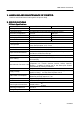
CBM-920 Service Manual 1. HANDLING AND MAINTENANCE OF PR PRINTER See the Instruction Manual coming with the printer body. 2. SPECIFICATIONS 2.1 Basic Specifications Item Printing Method Printing Direction Character Configuration Number of Digits Printing Speed Character Size Line Spacing CBM-920-24** CBM-920-40** Dot matrix Unidirectional printing (Erect/inverted characters) (5+1)´8 (4+0.5)´8 24 digits: 144 dots/line 40 digits: 180 dots/line Approx. 2.5 lines/sec. Approx. 1.8 lines/sec. 1.62´2.4mm 1.
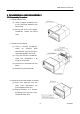
CBM-920 Service Manual 3. DISASSE SSEMBLY AND REASSE SSEMBLY 3-1 Disasse ssembly Procedure 1. Remove a shield cover. (1) Insert a regular screwdriver into a slot in the top(or bottom) of the shield cover. (2) Raising the end of the regular screwdriver, remove the shield cover. 2. Remove a control board. (1) Using a loosen Phillips an screwdriver, earthing plate setscrew(PHT, M2.6 X 8) and FG cable setscrew(PHT, M2.6 X 8). (2) Using the Phillips screwdriver, loosen two screws(M2.
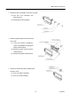
CBM-920 Service Manual · Remove an N-PE assembly from the front cover. (1) Pull out a PE retainer.(It has been press-fit) (2) Remove the N-PE assembly. · Remove a paper holder bracket from the front cover. (1) Using the Phillips screwdriver, loosen 4 screws(M2 x 6) fixing the paper holder bracket. (2) Remove an earth plate 2 and FG cable terminal. (3) Remove the paper holder bracket. · Remove an operation panel assembly from the front cover. (1) Pull out a switch assembly. (2) Pull out a LED assembly.
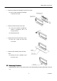
CBM-920 Service Manual · Remove a mechanical assembly from the front cover. (1) Pull out the mechanical assembly from the front cover. · Remove a knob from the front cover. (1) Using the Phillips screwdriver, loosen a screw(PHT, M2 x 6) fixing the knob. (2) Remove the knob. · Remove the rollers from the front cover. (1) Pull out a roller pin from the front cover. · Remove a PE assembly from the front cover. (1) Remove the PE assembly from the front cover.
CBM-920 Service Manual 4. TROUBLESHOOTING 4-1 Troubleshoot ooting Procedure When a trouble occurs, confirm its phenomenon, locate a defective part in accordance with 4-2 Troubleshooting Guide, and troubleshoot as described below. · Phenomenon: Find a trouble phenomenon in this column. If there are multiple phenomena, take all the corresponding items into consideration. This allows you to specify a hidden defective part. · Cause: Lists as many possible causes as possible.
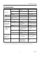
CBM-920 Service Manual 4-2 Troubleshoot ooting Guide Phenomenon Printing failure No printing Thin printing color Missing dots Bad printing quality Paper feed failure A printing paper feed motor does not function or malfunctions. The printing paper is not fed or fed irregularly.
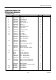
CBM-920 Service Manual 5. SERVICE PART ARTS LIST 5-1 Parts List for Me Mechanism EXPLODED VIEW Ref. No. Par ts No.
CBM-920 Service Manual 5-2 Disasse ssembly Drawing - 11 - CITIZEN
CBM-920 Service Manual 5-3 Parts List for Control Board 1/2 Ref. No. Par ts No.
CBM-920 Service Manual 2/2 Ref. No. Par ts No. Descri cription CBM920920-PF CBM920920-RF 1 1 3 CA 1 E 2000-090 Ca. Array C 1,6,7 C 2-5,8,18,19 C 2-5,8-18 C 9,14,16,24 C 10 C 10,19,22,23 C 13 C 15 C 17 C 20,21 C 25 E 2600-050 E 2600-090 E 2600-090 E 2600-120 E 2010-860 E 2010-860 E 2010-890 E 2010-870 E 2010-880 E 2010-900 E 2122-060 Chip C. Cap. GRM40F103Z50 Chip C. Cap. GRM40B471K50 Chip C. Cap. GRM40B471K50 Chip C. Cap. GRM40F104Z25 El. Cap. 25JS-10uF El. Cap. 25JS-10uF El. Cap. 50JS-1uF El.
CBM-920 Service Manual 5-4 Parts Layout Drawing 5-4-1 Main PCB Assy for CBM-920-PF (Parallel Interface) KJL-1 KJL-2 - 14 - CITIZEN
CBM-920 Service Manual 5-4-2 Main PCB Assy for CBM-920-RF(Serial Interface) KJL-1 KJL-2 - 15 - CITIZEN
CBM-920 Service Manual 5-4-3 Drawing for Jumper Lead - 16 - CITIZEN
CBM-920 Service Manual 6. DRAWING The following lists the reference drawings for maintenance, and so on.
CBM-920 Service Manual 6-1 Circuit 6-1-1 Block Diagram CBM-920 COVERALL WIRING DIAGRAM - 18 - CITIZEN
CBM-920 Service Manual 6-1-2 Coverall Wiring Diagram - 19 - CITIZEN
CBM-920 Service Manual 6-2 Circuit Diagram 6-2-1 CBM CBM-920-PF (Paralle llel Interface) - 20 - CITIZEN
CBM-920 Service Manual 6-2-2 CBM-920920-RF (Serial Interface) 5.