CITIZEN Service Manual Model: CBM1000 Line Thermal Printer Rev. 1.00 Newly issued on Sep. 14. 1999 Jap Japan CBM Corporation Information Systems Div.
CBM1000 Service Manual INTRODU ODUCTION This manual describes the disassembly, reassembly, and maintenance procedures of the line thermal printer CBM1000. It is intended for field maintenance men. FEATURES The CBM1000 is a compact-sized, line thermal printer developed for a variety of applications. It has abundant built-in features, and can be used as a data communication terminal, POS terminal, kitchen terminal and for other applications.
CBM1000 Service Manual CONTENTS 1. HANDLING AND MAINTENANCE OF PRINTER ..........................................................................5 2. SPECIFICATIONS ...............................................................................................................................6 2.1 3. DISASSEMBLY AND REASSEMBLY ................................................................................................7 3.1 4. 5. Basic Specifications ..............................................
CBM1000 Service Manual 6.2 7. Circuit Diagram ........................................................................................................................37 6.2.1 Control PCB Assy (Serial Interface D-sub 25)............................................................37 6.2.2 Control PCB Assy (Parallel Interface) ........................................................................38 OUTER DIMENSION ........................................................................................
CBM1000 Service Manual 1. HANDLING AND MAINTENANCE OF PRINTER See the User’s Manual coming with the printer body.
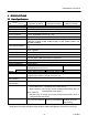
CBM1000 Service Manual 2. SPECI ECIFICATIONS 2.1 Basic Specifications Item Model Printing system Printing width Dot density Printing speed Printing columns Character size Character types Logo registration/print Bar code types Line spacing Paper Interface Input buffer Supply voltage Power consumption AC adapter spec.
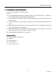
CBM1000 Service Manual 3. DISASSE SSEMBLY AND REASS REASSE SSEMBLY For maintenance operations, note the following: Notes: (1) Do not disassemble/reassemble or adjust the machine, if it functions properly. Particularly, do not loosen screws on any component, unless necessary. (2) After completing an inspection and before turning on the power, be sure to check that there is no abnormality. (3) During maintenance, be careful not to leave parts or screws unattached or loose inside the printer.
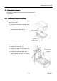
CBM1000 Service Manual 3.1 Disasse ssembly Procedure Disassembly procedure consists of the following two sections. • Main body • Mechanism 3.1.1 Disasse ssembly Procedure for Ma Main Body 1. Removing the Power Case SA (for AC Adaptrer Built-in Type) (1) Disconnect the power connector from the unit. (2) Remove the four screws M3 ×8 (ST) and detach the power case SA. Power Connector M3×8 (ST) Power Case SA 2. Removing the Printer Cover SA (1) Open the printer cover SA.
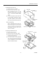
CBM1000 Service Manual 3. Removing the Top Cover SA (1) Remove the printer cover SA. (2) Remove the two screws M3 × 6 (ST). B Square Hole While unhooking the part “B” of the Top Cover SA M3×6 (ST) frame from the top cover SA, lift the top cover. At this time, avoid the power switch. (3) Unhook the operation panel cable from the cable holder, disconnect the operation panel connector from the control Operation Panel Connector PCB assy, and remove the top cover SA.
CBM1000 Service Manual Control PCB Assy 5. Removing the Control PCB Assy M3×6 (ST) (1) Remove the mechanism unit. (2) Remove the two screws M3 × 6 (ST). (3) Lift the front part of the control PCB assy to disengage the power switch from the switch guide of the bottom Power Switch chassis SA. Then pull the control PCB assy toward you to remove it. Switch Guide Bottom Chassis SA 6. Removing the AC Adapter (1) Remove the power case SA. (2) Cut the tie for the power cord.
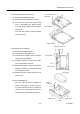
CBM1000 Service Manual 7. Removing the Tear Bar (1) Open the printer cover. Printer Cover (2) Remove the tear bar from the printer cover SA by pulling it as shown in the figure. Note on reassembling: When reassembling, press-fit it to the printer cover. Tear Bar 8. Removing the Operation Panel SA and Front Cover (1) Remove the top cover. Top Cover (2) Remove the operation panel SA to the front by pushing its back. Front Cover (3) Remove the front cover. Operation Panel SA 9.
CBM1000 Service Manual Serial IF Plate 10. Removing the Serial IF Plate (1) Remove the control PCB assy. Projection (2) Straighten the projections of the serial Bottom Chassis IF plate and remove it from the bottom chassis SA. (For serial IF type) (3) Remove the one screw M3 × 6 for frame ground (FG) and rubber feet from the M3×6 (ST, EXT, TW) bottom chassis. Rubber Foot 3.1.2 Disasse ssembly Procedure for Me Mechanism Unit 1.
CBM1000 Service Manual 2. Removing the Platen SA (1) While pushing the pressure Platen Bushing arm Platen SA downwardly, turn the platen bushing by 90 degrees in either direction. (Then, the flat surfaces of the left side platen bushing are set in vertical.) (2) Lift the left side platen SA to disengage it from the U-shaped groove on the main chassis. (3) Pull the platen SA to the left to remove it from the main chassis. Flat Surface Main Chassis Pressure Arm 3.
CBM1000 Service Manual 4. Removing the Gears (1) Remove the two screws M3 × 6 (ST) Main Chassis and remove the gear holder. (2) Remove the reduction gear and idle gear from the gear holder, in that order. Idle Gear Note on reassembling: Apply grease (Molykote EM-10L) to the shafts of the gear holder. Reduction Gear Gear Holder M3×6 (ST) 5. Removing the Auto Cutter SA Auto Cutter SA (1) Remove the four screws M3 × 6 (ST) and remove auto cutter SA. Main Chassis M3×6 (ST) 6.
CBM1000 Service Manual 7. Removing the Pressure Arms (1) Disengage the EXT spring-01 from the pressure arm-L and then remove the Main Chassis Pressure Arm-R M3×6 (ST) pressure arm-L from the main chassis. (2) Disengage the EXT spring-01 from the pressure arm-R and then remove the pressure arm-R from the main chassis. (3) Remove the one screw M3 × 6 (ST) from the main chassis. EXT Spring-01 Note on reassembling: Pressure Arm-L Securely insert the pressure arm-L/R into the screw heads. 8.
CBM1000 Service Manual 9. Removing the Top Chassis SA (1) Unhook the head cable assy from the Head Cable Assy cable holder. (2) Detach the wire. M3×6 (ST) (3) Remove the two screws M2.6 × 6 (BT) Damper and detach the head cover. (4) Remove the two screws M3 × 4 and detach the thermal head. Then, discon- nect the two connectors from the ther- M2.6×6 (BT) M3×4 Top Chassis Cable Holder Roller mal head.
CBM1000 Service Manual 11. Removing the Center Frame (1) Remove the PNE lever assy, sensor plate, guide roller and DIP SW cover Slider block. DIP SW Cover (2) Remove the one screw M2.6 × 6 (BT) Center Frame and detach the sensor PCB assy. Guide Roller (3) Remove the slider from the DIP SW cover. Note on reassembling: When reassembling the sensor PCB assy, hook its one end and then install it with the screw. Sensor Plate M2.6×6 (BT) Sensor PCB Assy PNE Lever Assy 12.
CBM1000 Service Manual 3.3 Lubrication Apply the specified lubricant to the indicated places. 3.3.1 Lubricant Grease: Molykote EM-10L 3.3.2 Where to Lubricate A. Platen bushings and the platen shafts (2 places each) B. Gear shafts of the gear holder (2 places) C. Sliding surface of the brake disc D. Lock shaft parts of the lock lever-R/L (2 places on both sides) (See the following figure.) E. Sliding parts of the pressure arm-R/L (3 places on both sides) (See the following figure.) F.
CBM1000 Service Manual 4. TROUBLESHOOT OOTING 4.1 Troubleshoot ooting Procedure When a trouble occurs, confirm its phenomenon, locate a defective part in accordance with 4.2 Troubleshooting Guide, and troubleshoot as described below. l Phenomenon: Find a trouble phenomenon in this column. If there are multiple phenomena, take all the corresponding items into consideration. This allows you to specify a hidden defective part. l Cause: Lists as many possible causes as possible.
CBM1000 Service Manual l Printing failure Phenomenon Cause Check Method Remedy No printing Faulty DC output volt- Check whether the Use the specified AC age from the AC specified AC adapter is adapter. adapter used. Faulty control PCB assy Replace the control PCB assy. Faulty connection of the Check connection of the Connect the thermal thermal head connector thermal head connector. head connector properly. Or replace the head cable assy. Faulty thermal head Replace the thermal head.
CBM1000 Service Manual l Paper feed eed failu ilure Phenomenon Cause Check Method Paper is not fed or Faulty connection of the Check connection of the fed irregularly motor connector motor connector. Defective motor Measure the supply voltage with a DC voltmeter or oscilloscope. Faulty DC output volt- Check whether the age from the AC specified AC adapter is adapter used. Low DC output voltage Check the DC voltage from the AC adapter with a DC voltmeter.
CBM1000 Service Manual l Faulty sensor Phenomenon Cause Check Method Does not detect Faulty paper sensor presence of paper. Check whether the ERROR lamp flickers when paper is out. Foreign substance is Check whether any forattached to the paper eign substances are sensor. adhered to the paper sensor. Faulty connection of the Check connection of the paper sensor connector paper sensor connector. Does not detect Faulty paper near-end paper near-end sensor status.
CBM1000 Service Manual 5. SERVICE PARTS LIST 5.1 Parts List for Me Mechanism EXPLODED VIEW Ref. No. 1/2 Parts No.
CBM1000 Service Manual EXPLODED VIEW Ref. No. 2/2 Parts No.
CBM1000 Service Manual 5.
CBM1000 Service Manual l Disasse ssembly Drawing-2 – 26 – CITIZEN
CBM1000 Service Manual 5.3 Parts List for Control PCB As Assy 5.3.1 Control PCB Assy ssy Ref. No 1/3 Parts No.
CBM1000 Service Manual 2/3 Ref. No Parts No. C101,103-109 C111,112,115 C125-127 Description CBM1000 CBM1000 R P C. Cap. C. Cap. C. Cap. GRM40CH101J50PT GRM40CH470J50PT GRM40F104Z50PT Re. Array BCN31-8SI332J Chip Re. CR10-332J 8 8 Chip Re. CR10-101J 6 6 Chip Re. Chip Re. CR10-303J CR10-103J 1 15 1 15 Chip Re. Chip Re. Chip Re. Chip Re. Chip Re. Chip Re. Chip Re. Chip Re.
CBM1000 Service Manual 3/3 Ref. No Parts No. Description CN3 CN4 CN5 CN6 CN7 CN8 CN9 CN10 CN11 E 48000945 E 48000755 E 48000765 E 48000955 E 48000930 E 48000755 E 48000950 E 48000705 E 48000640 CN11 E 48000645 E 48000830 1 1 1 1 1 (1) 1 1 (1) (JPN,EUR) or 17LE-13250-27 (D3CC) (1) (USA) Connector 57RE-40360-730B (D29A) S1 E 4003-630 SW. SF-W1P1A-01BB2 1 1 F1 F2 F3 E 4005-840 E 4005-770 E 4005-815 Fuse Fuse Fuse MS4 MO1.5 251.500 1 1 1 1 1 1 X1 E 501-430 X'tal CSTCV20.
CBM1000 Service Manual 5.4 Parts Layout Drawing 5.4.
CBM1000 Service Manual 5.4.
CBM1000 Service Manual 5.4.3 Operation PCB Assy ssy Ref.
CBM1000 Service Manual 5.4.4 Sensor PCB Ass Assy ssy Ref.
CBM1000 Service Manual 5.4.5 PNE PCB Ass Assy ssy in PNE Lever Assy ssy Ref.
CBM1000 Service Manual 6. DRAWING The following lists the reference drawings for maintenance, and so on.
CBM1000 Service Manual 6.
CBM1000 Service Manual 6.2 Circuit Diagram 6 .2 .
CBM1000 Service Manual 6.2.
CBM1000 Service Manual 7.
CBM1000 Service Manual l CBM1000 1000A/CBM100 1000D Unit: mm – 40 – CITIZEN
CBM1000 Service Manual l AC Adapter (31 AD) Unit: mm – 41 – CITIZEN