USER'S MANUAL Thermal Label & Barcode Printer CL-S521
CONTENTS Before Operation Introduction -------------------------------------------------------------------------- 3 COMPLIANCE STATEMENT FOR EUROPEAN USERS ----------------------------- 4 GS MARK STATEMENT -------------------------------------------------------------- 4 FCC COMPLIANCE STATEMENT FOR AMERICAN USERS ----------------------- 4 EMI COMPLIANCE STATEMENT FOR CANADIAN USERS ------------------------ 5 ETAT DE CONFORMITE EMI A L’USAGE DES UTILISATEURS CANADIENS ----- 5 Important Safety Instructions --
INTRODUCTION Thank you very much for purchasing Citizen's compact direct thermal label & barcode printer Model CL-S521 that offers high performance printing at 6 inches per second on 4.1 inch media at very low cost. ❚❚❚ Main Features ❚❚❚ This printer can be used for high-speed high-quality printing thanks to its thermal-transfer system that uses a line thermal printhead together with its 32 bit RISC CPU and its 'history control IC'.
COMPLIANCE STATEMENT FOR EUROPEAN USERS CE marking shows conformity to the following criteria and provisions: Low Voltage Directive (2006/95/EC, formerly 73/23/EEC)/EN60950-1 EMC Directive (2004/108/EC, formerly 89/336/EEC)/EN55022, EN55024, EN61000-3-2 & EN61000-3-3 GS MARK STATEMENT This product has been tested under EN ISO 7779 and has an acoustic level output no higher than 55db(A). This device is not intended for use at a video workstation in compliance with Bildscharb V.
EMI COMPLIANCE STATEMENT FOR CANADIAN USERS This Class A digital apparatus complies with Canadian ICES-003. This equipment generates and uses radio frequency energy and if not installed and used properly, that is, in strict accordance with the manufacturer's instructions, may cause interference to radio and television reception.
Important Safety Instructions • Read all of these instructions and save them for later reference. • Follow all warnings and instructions marked on the product. • Unplug this product from the wall outlet before cleaning. Do not use liquid or aerosol cleaners. Use a damp cloth for cleaning. • Do not use this product near water. • Do not place this product on an unstable cart, stand or table. The product may fall, causing serious damage to the product.
Notice • Before use, be sure to read this manual. And keep it handy for reference when needed. • The contents of this manual may change without prior notice. • Reproduction, transfer, or transmission of the contents of this manual without prior consent is strictly prohibited. • We are not liable for any damage resulting from the use of the information contained herein, regardless of errors, omissions, or misprints.
SAFETY INSTRUCTIONS which must be strictly observed ! • To prevent personal injury or property damage, the following shall be strictly observed. • The degree of possible injury and damage due to incorrect use or improperly following instructions is described below. Warning Indicates a situation which, if not observed and handled properly, could result in death or serious injury. Caution Indicates a situation which, if not observed and handled properly, could result in injury.
General Precautions Caution • Prior to operation, read the safety instructions carefully and observe them. • Do not drop or put foreign matter such as clips and pins into the printer. This may cause problems. • Be careful when moving or carrying the printer. Dropping the printer may cause injury or property damage. • Make sure if you open the top cover, it is opened all the way. If only partially open, the cover could slam shut, possibly causing injury.
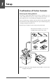
1 Setup Confirmation of Carton Contents Removing the Packing Material The printer is shipped with adhesive tape in place to hold the top cover closed. Simply remove the two pieces of tape on either side of the top cover. Then simply open the cover by lifting up and tipping it backwards. There is another strip of adhesive tape that must be removed which holds the mechanism closed for shipping. Remove the tape and attached paper by carefully peeling from the plastic case.
Setup Caution • Be careful when moving or carrying the printer and when taking the printer out of the carton. The printer may cause injury or property damage if dropped. Be sure to grip the printer housing firmly when taking it out of the carton. Do not grip the printer by the foam packing material which may break, causing the printer to drop. • When opening the cover, open it all the way. If only part way open, the cover could slam shut, possibly causing injury.
1 Setup Part Names and Functions 6 5 7 9 10 8 11 5 Media holder bar The media is supported by the media holder bar when installed in the printer. 6 Media holder guide This guide is moved horizontally to match the media size. The guide can be sliding it from the holder bar. 7 Motor cover It discharges the heat of the media feed motor. Do not cover it with media etc. 8 Front cover It is removed to install optional units such as the peeler or cutter. Media Width Adjustment (p.
Setup Part Names and Functions 17 12 15 14 -1 16 -1 14 -2 13 16 -2 = Thermal printhead This is the printhead. Avoid touching this with your fingertips and leaving grease or dirt on the printhead surface. ~ Platen Interlocked with the thermal printhead, it feeds media backwards or forwards. Setting sensor positions (p.23) Sensor Adjustments (p.
1 Setup Part Names and Functions Operation Panel 1 2 3 4 5 7 6 8 LED Functions (p.20) 1 POWER LED This is lit when the printer power is on. (green) 2 PRINT LED This is lit when the printer is able to print. (green) 3 CONDITION LED This is on when selecting settings. (orange) 4 ERROR LED This is lit or flashes when the printer is in an alarm or error status. (red) Normal Operating Mode (p.19) 5 PAUSE key This temporarily stops printing.
Setup Part Names and Functions Rear View 1 2 3 4 Serial interface (p.50) 1 Serial interface (RS232C) This receives serial transmission of data from a host computer. USB Interface (p.52) 2 USB interface This receives USB transmission of data from a host computer. Power ON/OFF (p.18) 3 Power switch The is the power switch for the printer. Connection to Power (p.16) 4 Power cord inlet The connector of the enclosed power cord is connected here.
1 Setup Connection to Power 1. Check that the power switch to the printer is turned OFF. 2. Connect the connector of the power cord to the power cord inlet on the printer. 3. Insert the plug of the power cord in the AC outlet. Power Switch AC Outlet Power Cord Inlet Caution Use an AC outlet that accepts a three-pronged plug. Otherwise, static electricity may be generated and there will be danger of electric shock.
Setup Connection to a Computer This product has two interfaces that can be used to receive printing data: a serial port (RS232C) and a USB port (USB1.1). An optional internal Ethernet, an IEEE1284 Parallel or Wireless LAN port can be added by your dealer. With the exception of a wireless LAN connection, an interface cable is necessary to connect the printer to a computer. To connect the cable, proceed as follows: 1. Turn OFF both power switches of the printer and the computer. 2.
2 Printer Operation Power ON/OFF Turning on the power 1. Turn on the power switch on the back of the printer. 2. The POWER and PRINT LED are lit. Operation Panel Power Switch Turning off the power 1. Turn off the power switch on the back of the printer. 2. The POWER and PRINT LED go off.
Printer Operation Normal Operating Mode Menu Setup Mode (p.27) When the power is turned on, the printer enters normal operating mode. The control keys activate the following functions. 1 3 2 4 1 PAUSE key: Temporarily pauses printing • When this key is pushed once, the PRINT LED turns off and the printer temporarily pauses. • When it is pushed during printing, the printer pauses after the label currently being printed is issued.
2 Printer Operation Normal Operating Mode LED Functions In addition to normal operating mode, when an abnormal condition is detected in the printer, an alarm sounds and each LED either lights up or flashes to indicate the type of error. 1 POWER LED 1 It lights up when printer power is turned on. (green) 2 2 PRINT LED 3 This is lit when the printer is able to print. (green) 4 3 CONDITION LED This is on when selecting settings.
Printer Operation Setting the Media Media Sizes The position of label and tag media is sensed by either a transparent sensor or a reflective sensor.
2 Printer Operation Setting the Media Installing the Media 1. Push the large blue-head open lever to release the head unit and sensor arm. It can be opened to the position shown below by lifting the head unit by hand. Large blue-head open lever 2. Firstly, slide the two black plastic parts of the media holder assembly together. Ensure correct alignment of the guide with the bar as it can only be installed in one direction. 3. Slide the roll of media over the media bar.
Printer Operation Setting the Media Sensor Selection Method (Transparent ↔ Reflective) (p.39) Adjusting the Transparent sensor (p.40) 6. Setting sensor positions. When using a transparent sensor Move the bottom sensor close to the center of the width of the media, then align the upper sensor marker and the bottom sensor marker (white) using the movable media guide.
2 Printer Operation Setting the Media 7. Align the media with the left fixed media guide, align the right movable media guide with the media width, and lower the sensor arm. Movable media guide Fixed media guide Sensor arm Media Thickness Adjustment (p.42) Media Width Adjustment (p.43) 8. Lower and lock the head unit. Align it with the width of the media that has been set, then set the media width and media thickness adjustment dials. See “Chapter 3 Printer Adjustments”.
Printer Operation Mode Settings Operation Panel (P.14) Turning on the power while pressing keys in the following combinations starts various functions. Mode Key operation HEX dump mode Turning power on while pushing the STOP key. Self print mode Turning power on while pushing the FEED key. Menu setting mode Turning power on while pushing the MODE/REPEAT key. HEX Dump Mode When using label media Turn on printer power while pushing the STOP key.
2 Printer Operation Mode Settings Self Print Mode Performing a self test print is an easy way to check on the state of printer setting and printing quality. Install the media as explained in “Installing the Media” and then operate the printer as follows. Setting the Media (P.21) Case of label media Turn on printer power while pushing the FEED key. When the PRINT LED has begun to flash slowly, release the FEED key. After it enters TEST MODE and media has fed, two labels print then printing stops.
Printer Operation Mode Settings Menu Setup Mode If the printer power is turn on while the MODE/REPEAT key is pressed, the printer enters menu setup mode. In this mode, the printer’s configuration can be changed using the VuePrint Menu System. During menu setting mode, the PRINT LED and CONDITION LED are on. Media must be installed in the printer to use the VuePrint menu system.
2 Printer Operation Mode Settings [Datamax® Emulation] Menu Setting Flow Chart The following is a flow chart showing the CL-S521 VuePrint menu system. 7 Datamax® Emulation Menu Setup Mode (p.27) Operation Panel MODE/REPEAT key + Power on Press FEED key for 3 seconds Printing during top menu setting (p.30) EXIT Do you want to reset this printer to factory settings? YES Are you sure? NO NO Initialization of the content of the settings (Initialization to the settings when the printer was shipped.
2 Printer Operation Mode Settings [Zebra® Emulation] 7 Zebra® Emulation Menu Setup Mode (p.27) Operation Panel MODE/REPEAT key + Power on Press FEED key for 3 seconds Printing during top menu setting (p.30) EXIT Do you want to reset this printer to factory settings? YES Are you sure? NO NO Initialization of the content of the settings (Initialization to the settings when the printer was shipped.) YES / Select / Save Next Digit Printing a list of settings (p.
2 Printer Operation Mode Settings Shown below is a sample menu output from the CL-S521 VuePrint menu system. This particular example is changing the print speed and print darkness then continues through the remainder of the “Print Setup” menu. The actual output from the printer is "vertically reversed" due to the way the printer outputs the menu options. Please look at the example below to see how the output changes. Menu Setting Flow Chart (p.
Printer Operation Mode Settings Menu Setting Flow Chart (p.28) Printing a list of settings Machine Information Model Number Boot Version ROM Version ROM Date (DD//MM//YY) ROM Check Sum Head Check Print Counter Service Counter Cut Counter Sensor Monitor Option Interface : CL-S521 : X.X : XXXXXXXX : XX/XX/XX : XXXX : OK : 0000.872 km : 0000.872 km : 83 : 2.
2 Printer Operation Mode Settings [Datamax® Emulation] Menu Setting Table Global Config menu - allows you to switch between 3 complete ‘config sets’ contained within the printer. Page Setup Menu - allows you to change settings related to the media or print quality. System Setup Menu - allows you to change settings for the printer hardware and basic control systems. After Print Menu - changes how the printer reacts after the label has been printed.
Printer Operation Mode Settings [Datamax® Emulation] Top Menu After Print Interface Sub Menu Default Menu Remarks Emulation Select DM4 DMI DM4 DPP ZPI2 Selects DataMax®/Zebra® compatibility DMI: DataMax® IClass DM4: DataMax® 400 like DPP: DataMax® Prodigy Plus® ZPI2: Zebra® Emulation Emulation Auto Detect On On Off Full Auto Selects the detection of Datamax® and Zebra® emulation. AutoConfigure On On Off Optional auto configure On .... Auto configure effective.
2 Printer Operation Mode Settings [Datamax® Emulation] Top Menu Sub Menu Default Menu Remarks RS-232C Stop bit 1 bit 1 bit 2 bits Sets the stop bit of the serial interface. RS-232C X-ON Yes Yes No Selects the X-ON flow control of the serial interface. IEEE1284 ON ON OFF Enable or disables the 'enhanced' features of the IEEE1284 parallel interface. Web Monitor* Auto Auto On Off Selecting the web monitor function. USB Device Class Printer Printer VCOM Selects the USB device class.
Printer Operation Mode Settings [Zebra® Emulation] 7 Zebra® Emulation Top Menu Sub Menu Default Menu Remarks Global configuration – Config Set 1 Config Set 1 Config Set 2 Config Set 3 Sets the Config Set. Page Setup Print Speed 4 IPS 2 to 6 IPS Printing speed setting (2 to 4 IPS with optional peeler.) Print Darkness 10 00 to 30 Print darkness setting (printhead temperature) Darkness Adjust 0 -10 to 10 Darkness command adjustment Continuous Media Length 4.00 IN 101.6mm 0.25 to 32.
2 Printer Operation Mode Settings [Zebra® Emulation] Top Menu Sub Menu Default Menu Remarks After Print AutoConfigure On On Off Optional auto configure On .... Auto configure effective. If a peeler unit or auto-cutter is installed, each mode is automatically set regardless of the “function select” setting. Off ... Auto configure ineffective. When a peeler unit or auto-cutter is installed but has not been started, it is off and the operation is selected by “Function select”.
Printer Operation Mode Settings [Zebra® Emulation] Top Menu Sub Menu Default Menu Remarks Web Monitor* Auto Auto On Off Selecting the web monitor function. USB Device Class Printer Printer VCOM Selects the USB device class. USB VCOM Protocol Auto Auto DTR X-ON Selects the protocol (flow control) when operating USB VCOM. * Displayed only when an optional LAN board is connected to a printer.
2 Printer Operation Emulation Auto Detect: Cross-EmulationTM Menu Setting Table (p.33, p.35) A different emulation will be detected when the Emulation Auto Detect of the System Setup is set to On or Full Auto. (Detects Zebra® when Datamax® is selected, and Datamax® when Zebra® is selected.) If the “Emulation Auto Detect” is set to “On” If the “Emulation Auto-Detect” is set to “On”, this will cause the CONDITION LED to flash when it detects an alternative emulation.
3 Printer Adjustments Sensor Adjustments The sensing level of both the transparent (see thru) and reflective sensors is adjusted separately and independently. Firstly, the sensor type must be selected either using the VuePrint menu system or the Sensor Method Selection shown below. Then the adjustment and calibration of the sensor can be made. Entering Sensor Adjustment Mode 1. Turn on the power while pushing the PAUSE key, FEED key, and STOP key simultaneously. Power Switch 2.
3 Printer Adjustments Sensor Adjustments Adjusting the Transparent sensor Media Setting (p.23) 1. Push the large blue-head open lever to open the head unit and sensor arm, then return only the sensor arm to its original position. Align the upper sensor marker and the bottom sensor marker (white) using the movable media guide. Upper sensor marker Upper sensor Alignment of markers Bottom sensor Transparent sensor marker Sensor Selection Method (Transparent ↔ Reflective) (p.39) Movable media guide 2.
Printer Adjustments Sensor Adjustments Adjusting the Reflective sensor 1. Open the printhead and the sensor arm, then align the position of the sensor marker of the bottom sensor is at the center of the black mark on the media. Black mark Media Bottom sensor Black mark Reflective sensor marker Sensor Selection Method (Transparent ↔ Reflective) (p.39) 2. Select the reflective sensor. 3.
3 Printer Adjustments Media Thickness Adjustment Installing the Media (p.24) It may be necessary to adjust the printer according to the thickness of the media being used. This can be done easily by rotating the media adjustment dial to improve the print quality. • Poor print quality across the complete printout means wrongly set media thickness. See this section. • Poor print quality on one side of a printout means wrongly set media width. See next section.
Printer Adjustments Media Width Adjustment Installing the Media (p.24) Self Print Mode (p.26) The head pressure varies according to the width of the media being printed. The head pressure balance must be adjusted according to media width so that constant head pressure is applied to the head. With this printer, it can be adjusted easily by turning the media width adjustment dial.
3 Printer Adjustments Cleaning Wipe off any foreign matter such as media dust, dirt and adhesive substances built up around the printhead with the head cleaning pen (head cleaner) provided, and use a soft cloth soaked in ethyl alcohol for the platen etc. It is particularly important to clean the thermal printhead after printing on thermal media for long periods, which will guarantee the print quality and extend the life of the thermal printhead.
4 Troubleshooting This chapter explains corrective actions taken when the printer malfunctions or when an error message is displayed. Items to check when a malfunction occurs When the printer malfunctions during operation, take corrective action with reference to the following table. If the corrective action does not solve the problem, consult with the service personnel at the dealer where you purchased the printer. Connection to Power (p.
4 Troubleshooting Indication Check Corrective action The printer is not printing neatly. 3) Is the thermal printhead dirty? Is a label stuck to the head. 3) If it is dirty, remove the dirt with the attached head cleaner. If a label is stuck to the head, remove it. Note: Do not use a metal object to remove a label stuck to the inside of the printer. (This may damage the print head.) If adhesive label material is stuck to the thermal printhead, remove it with a soft cloth soaked in ethyl alcohol.
Appendixes Specifications Item Printing Description Printing method Resolution Direct thermal Main scanning line density: 203 dots/inch (8 dots/mm) Sub- scanning line density: 203 dots/inch (8 dots/mm) Head 864 dots (effective dots: 832 dots) Printing speed Print mode Media Max. print width 104 mm 4.1 inch Max. print length 812.8 mm 32 inch Print density Print density is adjustable with software Printing speed setting 6, 5, 4, 3 or 2 inches per second.
Appendixes Specifications Item Bar code (for Zebra® emulation) Description One-dimension • Code 11 • Interleaved 2 of 5 • Code 39 • EAN-8 • UPC-E • Code 93 • Code 128 • EAN-13 • Industrial 2 of 5 • Standard 2 of 5 • ANSI CODABAR • LOGMARS • MSI • Plessey • UPC/EAN Extensions • UPC-A • POSTNET • Planet Two-dimension • Code 49 • PDF-417 • CODA BLOCK • UPS Maxi Code • Micro PDF-417 • Data Matrix • QR Code • RSS • TLC39 Font (for Datamax® emulation) 1.
Appendixes Specifications Item Power (standards) Description 100V version 100V, 50/60Hz (Japan) 120V (-10%+6%), 2.5A, 60Hz (U.S.A., Canada) UL60950-1, CSA No. 950, FCC Part 15 Subpart B (Class A) Environment 220V version 220V-240V (-10%+6%), 1.2A, 50/60Hz (Europe) EN60950-1, EN55022 (Class A), EN55024, EN61000-3-2, EN61000-3-3 Operating temperature conditions: Operating temp.
Appendixes Interfaces This printer is connected to a computer and prints according to commands sent from the computer. There are three types of computer interfaces, and these are connected to devices suited to each type of interface. The printer can also be connected to a computer by the optional Ethernet and wireless LAN.
Appendixes Interfaces XON/XOFF Protocol Requirements to output X-ON code • Communication is possible when the power is on. • When the receive buffer has less than 128 byte available, XOFF code is output, then the receive buffer has at least 1024 bytes available.
Appendixes Interfaces USB Interface Specifications Standards Complies with Universal Serial Bus Specification Transmission speed Compatible with 12Mbps (full speed) transmission Receive buffer 16kB Connector DUSB DUSB-BRA42-T11(DDK) Signal line and pin arrangement Pin No.
Appendixes Interfaces Parallel Interface (Option) Specifications Transmission mode 8-bit parallel data Receive buffer size 16kB Transmission modes Compatible mode It is an asynchronous forward direction of the byte width (from host to printer) channel, and the interface line of the data is operated in accordance with signal line definitions of Centronics. NIBBLE mode Nibble mode is asynchronous reverse channel communication with data transmission controlled by the host computer.
Appendixes Interfaces Parallel port status signals when an error occurs The status of a signal line will not be changed in bi-directional mode such as nibble or ECP mode.
Appendixes Interfaces [While receiving INIT signal] Min. 10 to 15µsec *Init BUSY *Ack *Fault SELECT Note: If the *Init signal does not have width of 10 to 15µsec or more, it cannot act as an Init signal. If it is lower, the *Init signal is ignored. BUSY starts up when the *Init signal is perceived.
363 Van Ness Way, Suite 404 Torrance, CA 90501. USA Tel: (310) 781-1460 Fax:(310) 781-9152 http://www.citizen-systems.com Mettinger Strasse 11 Park House, 643-651 Staines Road D-73728, Esslingen Feltham, Middlesex, TW14 8PA Germany United Kingdom Tel: +49 (0) 711 3906 400 Tel: +44 (0) 20 8893 1900 Fax:+49 (0) 711 3906 405 Fax: +44 (0) 20 8893 0080 http://www.citizen-europe.com 6-1-12, Tanashi-cho, Nishi-Tokyo-shi Tokyo, 188-8511. Japan Tel: +81 (0) 42 468 4608 Fax:+81 (0) 42 468 4997 http://www.