CLP-2001 User's Manual
FCC COMPLIANCE STATEMENT FOR AMERICAN USERS This equipment has been tested and found to comply with the limits for a Class A digital device, pursuant to Part 15 of the FCC Rules. These limits are designed to provide reasonable protection against harmful interference when the equipment is operated in a commercial environment.
EMI COMPLIANCE STATEMENT FOR CANADIAN USERS This equipment generates and uses radio frequency energy and if not installed and used properly, that is, in strict accordance with the manufacturer's instructions, may cause interference to radio and television reception. This digital apparatus does not exceed the Class A limits for radio noise emissions from digital apparatus set out in the Radio Interference Regulations of the Canadian Department of Communications.
Important Safety Instructions 1. Read all of these instructions and save them for later reference. 2. Follow all warnings and instructions marked on the product. 3. Unplug this product from the wall outlet before cleaning. Do not use liquid or aerosol cleaners. Use a damp cloth for cleaning. 4. Do not use this product near water. 5. Do not place this product on an unstable cart, stand or table. The product may fall, causing serious damage to the product. 6.
Notice 1. Before use, be sure to read this manual. And keep it handy for reference when needed. 2. The contents of this manual may be changed without prior notice. 3. Reproduction, transfer, or transmission of the contents of this manual without prior consent is strictly prohibited. 4. We are not liable for any damage resulting from the use of the information contained herein, regardless of errors, omissions, or misprints. 5.
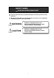
SAFETY SIGNS must be strictly observed ! To prevent personal injury or property damage, the following shall be strictly observed. The degree of possible injury and damage due to incorrect use or improperly following instructions is described below. WARNING Indicates a situation which, if not observed and handled properly, could result in death or serious injury. CAUTION Indicates a situation which, if not observed and handled properly, could result in injury.
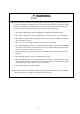
WARNING Never perform the following. If not avoided, these may cause damage or trouble to the printer or cause the printer to overheat and release smoke and cause burns or an electrical shock. If the printer is damaged or is malfunctioning, be sure to turn the power off immediately and remove the power cord from the outlet, then consult our service personnel. • Do not jolt or impact to the printer by stepping on, dropping or hitting the printer.
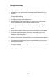
General precautions 1. Prior to operation, read the safety instructions carefully and observe them. 2. Do not drop any clips, pins or similar metals onto the printer, which may cause problems. 3. Be careful when moving or carrying the printer. Dropping the printer may cause injury or property damage. 4. Do not open the printer cover during printing. 5. When cleaning the surface of the printer case, do not use the cloth soaked in thinner, trichloroethylene, benzine, ketone or similar chemicals. 6.
Precautions when installing the printer 1. Prior to operation, read the safety instructions carefully and observe them. 2. Do not use or store the printer near fire, excessive moisture, in direct sunlight, near an air conditioner or heater or other source of unusually high or low in temperature or high humidity or excessive dust. 3. Do not place the printer where chemical reactions occur, such as in a laboratory. 4. Do not place the printer where air is mixed with salt or gas. 5.
Chapters in this manual Chapter 1 Setup Describes the packed items after opening the carton as well as the names and functions of parts. Chapter 2 Control Panel Describes the necessary items for operations, such as the control panel, printer settings and indications on the LCD/LEDs. Chapter 3 Paper and Ribbon Describes the procedures for loading the paper and ribbon including the notes on the use of paper and ribbon. Chapter 4 Troubleshooting Describes corrective actions when problems occur.
Table of Contents FCC Compliance Statement for American Users ..................... i EMI Compliance Statement for Canadian Users ...................... ii Important Safety Instructions .................................................... iii Notice ....................................................................................... iv Safety Signs Warning ........................................................................... v ......................................................................
Chapter 5 Options .............................................................................. 5-1 5.1 Auto-Cutter Unit 5.2 Peeler Unit 5.3 PCMCIA Memory Card Chapter 6 ............................................................ 5-2 ..................................................................... 5-2 ................................................. 5-3 Specifications ..................................................................... 6-1 6.1 Basic Specifications ....................
xii
Chapter 1 Setup 1.1 Confirmation of Carton Contents 1-2 1.2 Installing the paper holders 1-3 1.3 Names and Functions of the Parts 1-4 1.4 Connection to Power 1-8 1.
1.1 Confirmation of Carton Contents CAUTION Be careful when moving or carrying the printer and when taking the printer out of the carton. The printer may cause injury or property damage if dropped. Be sure to hold the printer firmly when taking it out of the carton. Do not grip the printer by the foam packing materials, which may break, causing the printer to drop. Check that the following accessories are included with the printer in the carton.
1.2 Installing the Paper Holders The roll paper of 4 in. diameter (102 mm diameter) is set on the back of the printer. Installation 1) Open the printer cover. 2) Set the paper holders as shown in the figure. 3) Secure the paper holders with screws M3 from the top and M4 from the back.
1.3 Names and Functions of the Parts Front view Control panel The control panel is a center of the printer that displays printer messages through the LCD and LEDs. 1) LEDs One LED is the power indicator and the other is the error indicator. 2) LCD Displays the current printer status, configuration settings and errors. 3) Control keys The Pause, Feed and Stop keys are arranged from left to right and are used to facilitate printer operating. (For details, see Chapter 2 Control Panel.
Inside view Printer cover Opens to allow loading of the paper and ribbon. Ribbon holder Holds the ribbon. (See Chapter 3.) Ribbon winder Winds the ribbon after printing. (See Chapter 3.) Roll holder Holds the roll paper. Roll guide Guide the roll paper to be set on the roll holder. The roll guide can be adjusted in accordance with the width of the paper. (See Chapter 3.) Paper holders Hold the roll holder to be inserted in the paper core. Head open lever Opens and closes the print head.
Printer cover Ribbon winder Ribbon holder Paper holder Roll holder Roll guide Head pressure check window Head open lever Offset check window 1-6
Side view Interface connectors Connect the interface cables. PCMCIA memory card cover To protect the PCMCIA memory card from exposure to dust and foreign matter. To install a PCMCIA memory card, first unhook this cover, then slide it out. Power switch Turns on and off the power to the printer. Power inlet Connects the power cord.
1.4 Connection to Power CAUTION Use the three-pin (including grounding) outlet. Otherwise, you may get a small shock by static electricity. Also, you may get an electric shock when the printer breaks down or short circuit occurs or a thunderbolt falls. Connect to power as follows: 1) Check that the power switch on the printer is turned off. 2) Connect the connector of the power cord to the power inlet on the printer. 3) Insert the plug of the power cord in the outlet.
1.5 Connection to a Computer An interface cable is necessary for connecting the printer to a computer. Connect the printer to a computer as follows: 1) Check that both printer and computer power switches are turned off. 2) Insert the connector of the interface cable in the interface connector on the printer and secure it with lock screws. 3) Insert the connector on the other side of the interface cable in the interface connector on the computer and secure it with lock screws.
1-10
Chapter 2 Control Panel 2.1 Control Panel 2-2 2.2 LCD/LED Indications and Adjustment Controls 2-3 2.3 Normal Operating Mode 2-3 2.4 Printer Setup Mode 2-4 2.5 Self-Test Mode 2-4 2.
2.1 Control Panel The control panel consists of the three control keys (Pause, Feed and Stop), two LED indicator lights (Power and Error), and LCD message screen. On the left side of the control panel there are three adjustment controls (paper gap sensor, black line sensor and LCD contrast).
2.2 LCD/LED Indications and Adjustment Controls 1) LCD The eight-character LCD screen displays the current printer status, configuration settings, or an error message. 2) LEDs Power: Lights when the power is tuned ON. Error: Lights or blinks when an error occurs. 3) Adjustment controls The three adjustment controls are used to adjust the paper gap (transparent type) sensor sensitivity, black line (reflective type) sensor sensitivity, and LCD contrast. 2.
2.4 Printer Setup Mode The printer enters the printer setup mode when both Pause and Feed keys are pressed simultaneously. The control key functions at this time are described below. Settings of the printer setup mode are stored in nonvolatile memory, so once they are set, they are remained even when the power is turned off. [Functions] Set the print mode selection, peeling sensor ON/OFF, auto-cutter ON/OFF etc. Pause key: Selects the mode. Feed key: Selects the mode item.
2.6 System Maintenance Mode The printer enters the system maintenance mode when the Pause, Feed and Stop keys are pressed and held down simultaneously while turning the printer on.
Voltage setting In the voltage setting mode, operate the paper gap and black line adjustment controls in the following way: For the standard paper gap voltage, both "PE" and "BL" displayed on the LCD screen are set to 3.0 V–3.3 V. Setting procedure: 1) Sets only the liner peeled off the label. (For the black line paper, set it so that black lines are off the paper sensor.) 2) Sets the paper gap level to 3.0 V–3.3 V by operating the adjustment controls.
Chapter 3 Paper and Ribbon 3.1 Kinds of Paper 3-2 3.2 Label and Tag Specifications 3-2 3.3 Ribbon 3-6 3.4 Loading the Paper 3-7 3.5 Loading the Ribbon 3-9 3.6 Print Head Offset Adjustments 3-10 3.
3.1 Kinds of Paper 1) Kinds of paper A thermal-transfer or direct-thermal printing paper can be used. The paper must be of high quality. Otherwise, the clear print quality and the longer life of the print head will not be guaranteed. 2) Type of paper • Labels (continuous, die-cut, fanfold) • Tags • Tickets Both in-wound and out-wound paper rolls may be used. 3) Size of paper Width of paper: 25.4 mm–118 mm (1 in–4.65 in) Thickness of paper: 0.063 mm–0.254 mm (0.0025 in–0.01 in) Max.
Minimum value mm (in) Maximum value mm (in) A Width of label 25.4 (1.0) 118 (4.65) B Width of liner 25.4 (1.0) 118 (4.65) C Left edge of label 0 2.54 (0.10) D Length of paper gap between labels 2.54 (0.10) 2539 (99.96) E Length of label 12.7 (0.50) 2539 (99.96) F Pitch of label 12.7 (0.50) 2539 (99.96) G Thickness of liner 0.06 (0.0025) 0.125 (0.0049) H Overall thickness of paper 0.06 (0.0025) I Right end of notch J Left end of notch 0 K Length of notch 2.54 (0.
3-4
Units for specifying position and length The print position may be specified in either inch or metric system. Switching between the two systems is accomplished through software. The print position can be freely designated within the maximum label size, regardless of which system you wish to use. Inch system Basic unit (point): 0.01 in (0.254 mm) The position of each row address (in direction of main scanning) and column address (in direction of sub-scanning) is designated in 0.01inch units.
Reference points The reference points are described in the figure. The position of 2.5 mm from the left edge of the paper is the reference point. The left bottom is the reference point for the printed characters and bar codes. The concept of this reference point is common to such commands as ruled line and graphic. Printing reference point Printing reference point 2.5 Left edge of paper Paper reference line Printing reference point Printing reference point Direction of paper feed 3.
3.4 Loading the Paper CAUTION Be careful of the edges of the plates so injury or property damage is possible. The printer is designed to easily load the paper and ribbon. After opening the cover, set the register paper as follows: 1) Push down the open lever (1) to have the head open (see the figure). 2) Push the lever (3) to have the guide rail upper (2) open. 3) Insert the roll holder (4) in the roll paper and roll guide (5) and set on the paper holder (6).
10 1 2 Roll paper 5 4 6 3 Reference plane 7 8 Positioning notch 3-8 9
3.5 Loading the Ribbon CAUTION Be careful of the edges of the plates so injury or property damage is possible. After opening the cover, set the ribbon as follows: 1) Push down the open lever (1) to have the head open (see the figure). 2) Insert the ribbon shaft (11) in the ribbon until it reaches the end. Then set the ribbon holder as shown in the figure. 3) Insert the ribbon shaft (12) in the paper core (13) until it reaches the end. Then set the ribbon winder as shown in the figure.
3.6 Print Head Offset Adjustments CAUTION Ensure the print head offset adjustments are correct for your type of print media (thickness & width). Incorrect adjustments can cause premature failure of the print head. The printer has already been factory-set to the label paper with a width of 112 mm (4.4 in). However, the print head offset adjustments might be necessary depending on the width of the paper and the paper quality.
2. When the print density on the left and right sides is not equal (when the paper with a different width has been used): The right head pressure viewed from the front of the panel can be adjusted with the head pressure adjust-screw. Turning the adjust-screw clockwise decreases the head pressure and turning the adjust-screw counterclockwise increases the head pressure.
3.7 Ribbon Tension Adjustments When the ribbon slips or wrinkles during printing, adjust the ribbon tension. The printer has already been factory set with the ribbon width of 114 mm. When using ribbon with a different width, adjust it according to the following procedure: a) Hold the ribbon roll with one hand so that it does not turn. b) Slightly push the knob toward the ribbon roll with the other hand and rotate the knob until the stopper comes to the desired position.
Chapter 4 Troubleshooting 4.1 Error Messages 4-2 4.1.1 Error descriptions and indications 4-2 4.1.2 Error indications and corrective actions 4-4 4.2 Power Troubleshooting 4-7 4.3 Paper Feed Troubleshooting 4-8 4.4 Ribbon Feed Troubleshooting 4-9 4.5 Print Troubleshooting 4-10 4.
4.1 Error Messages When there is a problem with the printer, a buzzer sounds, and the LED error indicator on the control panel lights. An error message is displayed on the LCD screen. Error descriptions and corrective actions are shown below. 4.1.
Description LCD indication Paper out (paper position can't be detected) Error contents and sensor information repeatedly displayed PaperErr M command: Sets length for detection miss checking with system command M M CMND Maximum: Max. value of sensor reading voltage Max*.**V Minimum: Min. value of sensor reading voltage Min*.
4.1.2 Error indications and corrective actions LCD indication Battery Description Battery dead Corrective actions Automatically returned after displaying the error for a certain time. Change the lithium battery (CR2032). Note: Contact our service personnel for replacing the battery If the battery runs down, the real-time clock will stop and the contents of the memory switch will be lost. ColdHead Low head temperature Automatically returned after displaying the error for a certain time.
LCD indication Pause Description Pause key pressed Corrective actions Press the Pause key once again to resume printing. If the Stop key is pressed, the stored printing contents will be lost and "on line" will turn on. Pause Pause command reception (communication control) Same as above. OverHeat Cooling Head overheat Wait until the head temperature goes down. When the temperature becomes low, the remaining printing resumes.
LCD indication Description Corrective actions PaperEnd Paper end (no paper left) Install the paper. PaperErr Paper out (paper position can't be detected) Check the contents and clear with the Stop key. Correct the faulty setting of the paper detection (paper gap, black line, continuous paper). Correct the faulty parameter for paper (max. length, continuous paper). Adjust the sensor or change for the paper that can accept the paper position detection.
LCD indication Description Corrective actions ROM Err ROM checksum error Turn off the power and reset the printer. If this recurs, contact our service personnel. RAM Err RAM checksum error Turn off the power and reset the printer. If this recurs, contact our service personnel. –– System error (such as timer or CPU running out of control). System is protected and the printer is reset First protect the system, then reset the printer. 4.
4.3 Paper Feed Troubleshooting Problem Paper doesn't feed. Paper is skew. Paper doesn't align with print position. Cause and remedy • Paper path is wrong. → Use the proper path. • Mechanism head is open. → Close the mechanism head. • Paper end is not in contact with the paper guide. → Slightly push the paper guide against the paper end. • Roll guide is not in contact with the roll paper. → Slightly push the roll guide against the roll paper. • Head pressure is not proper.
4.4 Ribbon Feed Troubleshooting Problem Cause and remedy • Ribbon path is wrong. → Use the proper path. • Direction of ribbon winding is reverse. → Set it to the right winding direction. • Tension of ribbon winding is not proper. → Set it properly. Printing continues even when ribbon is out. • Print mode is the directthermal. → Set it to the thermal-transfer if necessary. Ribbon wrinkles. • Tension of the ribbon holder and winder is not proper. → Set it properly.
4.5 Print Troubleshooting Problem Printing doesn't start. Cause and remedy • Power to the printer is off. → Turn on the power switch. If power is not still turned on, follow the steps in the Power Troubleshooting. • Printer is not properly connected to a computer. → Turn off the power switch and connect it properly. • Printer setting is not proper. → Correct the printer setting. Missing all lines. Partially dropouts. • Print head connector connection failure.
Problem Print is too light or dark. Other print abnormalities 4.6 Cause and remedy • Paper and ribbon are not the specified type. → Change to the specified type after checking the paper and ribbon makers and identification numbers if necessary. • Present paper quality doesn't match the print head offset. → Adjust the offset. See Print head offset adjustments. • Present width of the paper doesn't match the print head offset. → Adjust the offset. See Print head offset adjustments.
4-12
Chapter 5 Options Factory or reseller (dealer) options: 5.1 Auto-Cutter Unit 5-2 5.2 Peeler Unit 5-2 5.3 Adjustable Sensor 5-2 User options: 5.4 PCMCIA Memory Card 5-3 5.
5.1 Auto-Cutter Unit The auto-cutter unit that has been installed on the printer will be available. See the operation manual of the auto-cutter for details. Specifications 5.2 • Cutting method: Circlular cutter • Max. thickness of cut paper: 0.01 in (0.25 mm) • Min. length of cut paper: 1.0 in (25.4 mm) Peeler Unit The peeler unit that has been installed on the printer will be available. See the operation manual of the peeler unit for details. Specifications 5.3 • Width of paper: 1–4.65 in (25.
5.4 PCMCIA Memory Card The PCMCIA memory card is used to: 1) Store the print format files. Data in the field register area can be stored and loaded. 2) Store graphic data. For example, graphic data such as a corporate logo can be stored and recalled from the PCMCIA memory card and printed. Note: The maximum size of storing graphic data is 256K bytes. 3) Store downloaded HP Soft fonts. Installation 1) Turn off the power to the printer.
5.5 8-in Size Roll Paper Holder 8-in size roll paper holder • Max. outer diameter: 8 in (203 mm) • Paper core inner diameter: 1.
Chapter 6 Specifications 6.1 Basic Specifications 6-2 6.2 Interface 6-5 6.2.1 Serial interface system configuration 6-5 6.2.2 Parallel interface system configuration 6-6 6.2.3 RS-232C loopback test 6-7 6.2.4 RS-232C protocol 6-7 6.2.5 Interface pin assignment 6-9 6.3 Outline of Command System 6-11 6.4 Example of Connection to a Computer 6-12 6.5 Tear-Off Function 6-13 6.5.1 Turning Tear ON/OFF 6-13 6.5.2 Tear-off when printing 6-13 6.5.3 Tear-off when feeding 6-14 6.5.
6.1 Basic Specifications Item Printing Description • Direct-thermal or thermal-transfer • 203 dpi (8 dots/mm) print head (Main scanning line density: 8 dots/mm) (Sub-scanning line density: 8 lines/mm) • Max. printing width: 4.1 in (104 mm) • Max. paper width: 4.65 in (118 mm) • Max.
Item Standard fonts Description • Font No. 0–6 system font (alphanumeric and European font) • Font No. 7–8: OCR-A OCR-B • Font No. 9: CG Triumvirate smooth fonts; 6 pt, 8 pt, 10 pt, 12 pt, 14 pt, 18 pt, 24 pt, 30 pt, 36 pt, and 48 pt.
Item Communication interface Description • Serial: RS-232C • Parallel: Centronics Indications, keys and switches • LEDs: Power and Error • LCD: Displays printer status, error contents, mode switch contents, etc • Control panel keys: Pause, Feed and Stop • Mode switch: Parameter setting for switching between direct-thermal and thermaltransfer, communication etc.
6.2 Interface The printer is connected to a computer and prints labels according to the commands from the computer. Two methods of interface with a computer are as follows: 6.2.
6.2.
6.2.3 RS-232C loopback test After connector wiring as shown in the figure, turn on the test mode. The printer will receive data that has been transmitted by printer itself and the test of receiving and transmitting data will be performed. Fig. RS-232C loopback test 6.2.4 RS-232C protocol (1) X-ON/X-OFF system (see figure) This is a control system in which the data transmitting request signal (X-ON (11H) code) and the data transmitting stop signal (X-OFF (13H) code) are output.
Receive buffer size = 32K bytes 4K bytes 2K bytes Receiving data X-ON code output Note: X-OFF code output Even if each code is ready for output, the same code cannot be transmitted twice successively (except when the power is turned on or the printer is reset from the control panel). Fig. Buffer in use (2) Ready/Busy system (see figure) This is a control system in which the DTR is output at Ready (High) or Busy (Low) level.
6.2.5 Interface pin assignment Serial and parallel interface pin assignment tables are shown below. Serial interface pin assignment table Pin No. Signal Input/Output − Description 1 F.GND Frame ground 2 TXD Output 3 RXD Input 4 RTS − 5 CTS Input 6 NC − Not connected 7 S.GND − Signal ground 8 NC − Not connected 9 NC − Not connected 10 NC − Not connected 11 NC − Not connected 12 NC − Not connected 13 S.GND − Signal ground 14 +5VDC − +5 V (max.
Parallel interface pin assignment table Pin No. Signal Input/Output Description 1 STROBE Input Strobe signal for 8-bit data 2−9 DATA1-8 Input 8-bit parallel signal 10 ACKNLG Output 8-bit data request signal 11 BUSY Output Signal showing printer busy 12 PERROR Output Signal showing paper out 13 SELECT Output Signal showing printer "on line" (printing) or "off line" (pause) 14 AUTOFD Input 15 NC − Not used 16 S.GND − Signal ground 17 FGND − Frame ground 18 P.L.
6.3 Outline of Command System For details about command system, see the Command Reference separately available. Commands for this printer consist of a string of ASCII codes and end with "CR" (decimal: 13, hex: 0D). Commands are generally classified into two types, system-level commands and label format commands. System-level commands are used for system-level operations such as printer status output, sensor selection and memory card maintenance.
6.4 Example of Connection to a Computer When RS-232C is used: IBM PC compatible Communication control: XON/XOFF or CTS/DTR “PC” (DB25P) Printer (DB25P) F.GND 1 1 F.GND TXD 2 3 RXD RXD 3 2 TXD CTS 5 20 S.GND 7 7 S.GND DSR 6 4 RTS DTR 20 5 CTS “PC” (DB9P) DTR (Ready/Busy) Printer (DB25P) NC 1 F.GND TXD 3 3 RXD RXD 2 2 TXD CTS 8 20 BUSY S.GND 5 7 S.
6.5 Tear-Off Function The tear-off function eliminates the waste of labels when tearing manually. It allows the paper to automatically advance to the tear position after printing. When this function is turned on, the paper will be fed to the manual tear position after printing. The printer will feed back paper to the start print position when the next print job is sent. If data is transmitted continuously from the computer, the tear-off function will be suppressed to increase throughput. 6.5.
• The paper is fed to the tear position Paper position sensor Tear-off function will start if no data is sent for 0.5 second after printing Print head Platen Peeling (manual tearing) Paper is fed to the position where manual tearing is possible • When manual tearing is needed, tear the label at this time. • Performs next label printing. When next print data is transmitted from the computer, the printer feeds back paper to the previous print completed position and resumes printing.
6.5.4 Tear-off and type of data When the tear-off is valid, the printer monitors the print data for 0.5 second during or after printing. If print data is transmitted within 0.5 second during or after printing, the printer will start the next printing without tear-off. (When data is received during printing, the time of monitoring 0.5 second is not inserted.
• Parameter initial values Initial values of print and feed positions are described below. Unit: mm (inch) Normal printing Autocutter Peeling Tear-off Minimum value Print position (Onnnn, form offset) 55.9 (2.2) 55.9 (2.2) 55.9 (2.2) 55.9 (2.2) 12.7 (0.5) Feed position (fnnn) 55.9 (2.2) * * 70.1 (2.8) 12.7 (0.5) If values lower than the minimum values are set, initial values will be set instead. (For values with mark*, see the separate option operation manuals.) 6.5.
Citizen America Corporation 2102 Alton Parkway - Unit A Irvine, CA 92606 Tel: (949) 838-0327 U.S.A. Citizen Systems Europe GmbH http://www.citizen-europe.com Mettinger Strasse 11 Park House 73728 Esslingen 643-651 Staines Road, Feltham Germany Middlesex, TW14 8PA United Kingdom Japan CBM Corporation CBM Bldg.