
User`s manual


— 29 —
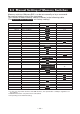
5.3 Manual Setting of Memory Switches
Memory switches (Memory SW) can be set manually or by a command.
For manual setting, refer to the next page.
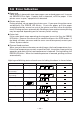
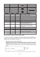
The function of each memory switch is shown in the following table.
(The white-on-black characters are factory setting.)
Switch No. Setting 0 (OFF) 1 (ON)
Memory SW1-1 Power ON Info Valid Not send
SW1-2 Buffer Size*1 4k bytes 45 bytes
SW1-3 Busy Condition Full/Err Full
SW1-4 Receive Error Print ? No Print
SW1-5 CR mode Ignored LF
SW1-6 Reserved Fixed −
SW1-7 DSR Signal Invalid Valid
SW1-8 Reserved Fixed −
Memory SW2-1 Reserved − Fixed
SW2-2*2 Auto Cutter Invalid Valid
SW2-3 Spool Print Invalid Valid
SW2-4 Full Col Print LineFeed WaitData
SW2-5 Resume aft PE Next Top
SW2-6 Reserved Fixed −
SW2-7 Reserved Fixed −
SW2-8 Reserved − Fixed
Memory SW3-1 Resum Cttr Err FEED switch valid FEED switch invalid
SW3-2 Reserved Fixed −
SW3-3 Parallel reset Valid Invalid
SW3-4 Reserved Fixed −
SW3-5 Character size*3 48 (CT-P292/CT-P293) 32
34 (CT-P290/CT-P291) 32
SW3-6 Reserved Fixed −
SW3-7
CBM1000 Mode
Invalid Valid
SW3-8
Resum Open Err
Close Command
Memory SW4-1 Reserved − Fixed
SW4-2 Reserved − Fixed
SW4-3 Feed&Cut at TOF − Fixed
SW4-4 Reserved Fixed −
SW4-5 Reserved Fixed −
SW4-6 Reserved Fixed −
SW4-7 Reserved Fixed −
SW4-8 Partial only Invalid Valid
*1. In the case of parallel interface and USB interface, the input buffer is 4 Kbytes regardless of
this setting.
*2. MSW2-2 functions only when DS1 is ON (Valid).
*3. Depending on the DSW-6 setting.