
Printer User Manual
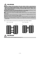
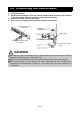
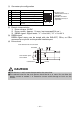
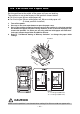
Table Of Contents
- WEEE MARK
- Declaration of Conformity
- GENERAL PRECAUTIONS
- SAFETY PRECAUTIONS
- THE TABLE OF CONTENTS
- 1. GENERAL OUTLINE
- 2. EXPLANATION OF PRINTER PARTS
- 3. SETUP
- 3.1 Connecting the AC Power Cord
- 3.2 Connecting Interface Cables
- 3.3 Connecting the Cash Drawer
- 3.4 Precautions for Installing the Printer
- 3.5 Partition for Paper Roll
- 3.6 Setting the DIP Switch on the Serial Interface Board
- 3.7 Adjusting the Paper Near-end Sensor
- 3.8 Loading Paper
- 3.9 Attaching the Power Switch Cover
- 3.10 Attaching the Interface Cover
- 3.11 Removing the Interface Cover
- 4. MAINTENANCE AND TROUBLESHOOTING
- 5. OTHER
—19—
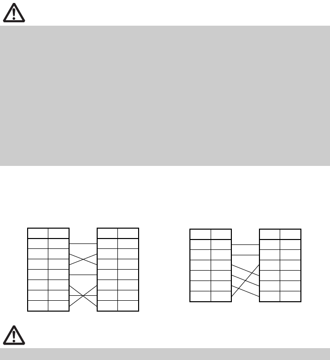
Use a serial interface cable with the connection layout shown below.
CAUTION
Always unplug the AC adapter from the printer before connecting the
printer to a Powered USB interface. Failure to do so may damage the host
PC. For information about installing a Powered USB interface, contact your
Citizen Systems dealer.
Check the orientation of the Powered USB cable connector before connecting it. Insert
it straight in so that the pins do not bend. Push it in until it clicks.
When disconnecting the cable, always hold the connector.
Be careful not to insert the USB interface cable into the cash drawer kick-out
connector.
To connect more than one printer to a single computer via a USB interface you must
change the serial number of the USB interface.
Hold the connector of the Ethernet interface cable perpendicular and straight when
connecting or disconnecting it. Doing it at an angle may cause the connector to
misconnect.
CAUTION
Place the interface cable so people do not trip on it.
25-pin - 25-pin cable
PC Printer
Signal
Pin Pin
Signal
RXD 2 2 TXD
TXD 3 3 RXD
DTR 4 4 RTS
SG 5 6 DSR
DSR 6 7 SG
CTS 8 20 DTR
9-pin - 25-pin cable
PC Printer
Signal
Pin Pin
Signal
FG 1 1 FG
TXD 2 2 TXD
RXD 3 3 RXD
CTS 5 4 RTS
DSR 6 6 DSR
SG 7 7 SG
DTR 20 20 DTR