NetScaler 9000 Series Installation and Configuration Guide - Vol. 1 180 Baytech Drive San Jose, CA 95134 Phone: 408-678-1600, Fax: 408-678-1601 www.netscaler.com NetScaler Part No.
© NETSCALER, INC., 2005. ALL RIGHTS RESERVED. NO PART OF THIS DOCUMENT MAY BE REPRODUCED OR TRANSMITTED IN ANY FORM OR BY ANY MEANS OR USED TO MAKE DERIVATIVE WORK (SUCH AS TRANSLATION, TRANSFORMATION, OR ADAPTATION) WITHOUT THE EXPRESS WRITTEN PERMISSION OF NETSCALER, INC. ALTHOUGH THE MATERIAL PRESENTED IN THIS DOCUMENT IS BELIEVED TO BE ACCURATE, IT IS PRESENTED WITHOUT WARRANTY OF ANY KIND, EXPRESS OR IMPLIED.
Contents Contents Chapter- 1 Introduction to the NetScaler 9000 Series. . . . . . . . . . . . . . . . . . . . . . . . 1-1 1.1 - Who Should Use This Book. . . . . . . . . . . . . . . . . . . . . . . . . . . . . . . . . 1-1 1.2 - How to Use The NetScaler 9000 Series Guides . . . . . . . . . . . . . . . . . 1-2 1.3 - Documentation Conventions . . . . . . . . . . . . . . . . . . . . . . . . . . . . . . . . 1-5 1.4 - The NetScaler 9000 Series . . . . . . . . . . . . . . . . . . . . . . . . . . . . . . . . .
Contents Chapter- 4 NetScaler Statistical Utility . . . . . . . . . . . . . . . . . . . . . . . . . . . . . . . . . . . . 4-1 4.1 - Overview . . . . . . . . . . . . . . . . . . . . . . . . . . . . . . . . . . . . . . . . . . . . . . . 4-1 4.2 - Accessing NetScaler Dashboard . . . . . . . . . . . . . . . . . . . . . . . . . . . . . 4-2 4.3 - Understanding Graphs and Legends. . . . . . . . . . . . . . . . . . . . . . . . . . 4-6 4.4 - Dashboard Components . . . . . . . . . . . . . . . . . . . . . . . . . . .
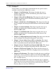
Chapter 1: Introduction to the NetScaler 9000 Series Chapter 1 Introduction to the NetScaler 9000 Series Welcome to the NetScaler 9000 Series Installation and Configuration Guide. This guide describes how to install, configure and manage all of the products included in the NetScaler 9000 product line and includes several sample configurations to assist you in planning for system deployment in your own network environment.
Chapter 1: Introduction to the NetScaler 9000 Series Knowledge of the software and services running on web servers is needed to configure the system appropriately. Basic knowledge of networking and web technologies is assumed. 1.2 How to Use The NetScaler 9000 Series Guides To help you use the NetScaler 9000 system and it’s various features, this documentation set is contained in two volumes. These volumes are organized as follows. 1.2.
Chapter 1: Introduction to the NetScaler 9000 Series 1.2.2 Volume 2 In this Volume, you will find the documentation for the specific features available on the NetScaler 9000 Series system. z Chapter 1, Load Balancing: This chapter describes the steps to configure and manage various Load Balancing (LB) feature in the NetScaler 9000 system. z Chapter 2, Firewall Load Balancing: This chapter describes the steps to configure and manage the the Firewall Load Balancing feature in the NetScaler 9000 system.
Chapter 1: Introduction to the NetScaler 9000 Series 1-4 z Chapter 12, Sure Connect: This chapter describes the steps to configure and manage the SureConnect feature in the NetScaler 9000 system. z Chapter 13, Advanced Network Configurations: This chapter describes how to configure advanced features such as, Layer 2 Mode, Use Source IP addresses (USIP), MAC-based Forwarding and VLANs support in the NetScaler 9000 system.
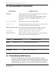
Chapter 1: Introduction to the NetScaler 9000 Series 1.3 Documentation Conventions CONVENTION ALERTS YOU TO: This typeface represents a command that you must type using the exact upper/lower case characters shown. Command After every command typed into the NetScaler 9000 Command Line Interface (CLI) press the Return or Enter key on your keyboard. Command argument This typeface represents a command argument.
Chapter 1: Introduction to the NetScaler 9000 Series 9000 Series is comprised of three products: the Secure Application Accelerator (9050/9100/9500), the Secure Application Gateway (9200/9600/ 9900) and the Secure Application Switch (9400/9800/9950). Each of these solutions is available in Fast Ethernet and gigabit configurations and can be integrated into any environment as a complement to existing load balancers, servers, caches and firewalls.
Chapter 1: Introduction to the NetScaler 9000 Series Table 1-1 Secure Application Accelerator product line. Model Number 9050 / 9100 9500 Network Interface 2 10/100 Base-T Ethernet ports 4 10/100/1000 BaseT or 4 Gigabit SX ports 1 10/100/1000 Base-T management port Key Packaged Features Application Security z L2-4 DoS Protection z SSL VPN (1 concurrent user session) Application Optimization z TCP Offload z SSL Offload z Compression 1.4.
Chapter 1: Introduction to the NetScaler 9000 Series Table 1-2 Secure Application Gateway product line: Model Number 9200 9600 Network Interface 2 10/100 Base-T Ethernet ports 4 10/100/1000 Base-T or 4 Gigabit SX ports 1 10/100/1000 Base-T management port 9900 4 10/100/1000 Base-T or 4 Gigabit SX ports 1 10/100/1000 Base-T Mgmt.
Chapter 1: Introduction to the NetScaler 9000 Series Table 1-3 Secure Application Switch product line Model Number 9400 9800 Network Interface Key Packaged Features 2 10/100 Base-T Ethernet ports 4 10/100/1000 Base-T or 4 Gigabit SX ports 1 10/100/1000 Base-T management port 9950 Application Security z L2-7 DoS Protection z Content Filtering z Surge Protection z Priority Queuing z SureConnect™ 4 10/100/1000 Base-T or 4 Gigabit SX ports z SSL VPN (5 concurrent user sessions) 1 10/100/1000
Chapter 1: Introduction to the NetScaler 9000 Series performance through the integration of in-memory static and dynamic caching. 1.4.6 Secure Remote Access User Packs For those businesses that wish to increase the capacity of the Secure Remote Access (SSL VPN) feature in the NetScaler 9000 Series, additional user packs are available as a means of boosting the number of concurrent user sessions supported.
Chapter 1: Introduction to the NetScaler 9000 Series 1.5.2 Application Security Features The Product Name (short) system includes the following traffic security features: z SSL Off load and Acceleration z Secure Remote Access (via SSL VPN) z Distributed Denial of Service Attack (DDoS) Defense z Content Filtering z Surge Protection z Priority Queuing z SureConnect™ 1.5.2.
Chapter 1: Introduction to the NetScaler 9000 Series system identifies legitimate clients and elevates their priority, leaving suspect clients unable to consume resources at a rate that would otherwise cripple a site. The NetScaler 9000 system provides application-level protection from other malicious attacks including SYN flood attacks, pipeline, teardop, land, fraggle, and zombie connection attacks.
Chapter 1: Introduction to the NetScaler 9000 Series resources become available. Because the surge of traffic has not been passed to the server, the server resources are preserved assuring all users of a better and more consistent experience. 1.5.2.6 Priority Queuing When a site is in a surge condition and clients are contending for access to server resources, the NetScaler 9000 system can prioritize user request to ensure that the most important traffic is serviced first.
Chapter 1: Introduction to the NetScaler 9000 Series 1.5.3.1 Compression The NetScaler 9000 system provides transparent compression for HTML and text files. The typical 4:1 compression yields up to 50% reduction in bandwidth requirements out of the data center. This also results in significantly improved end-user response time by reducing the amount of data that must be delivered to the browser. 1.5.3.
Chapter 1: Introduction to the NetScaler 9000 Series freeing up resources for new requests. This also permits the NetScaler 9000 system to optimize the TCP parameters for each of these clients and fully manage any retransmissions of dropped packets. 1.5.3.5 Consolidated Web Logging The NetScaler 9000 system's web server logging feature offloads the logging function from a server or cache to central location.
Chapter 1: Introduction to the NetScaler 9000 Series conventional approach of distributing connections among these systems. Load balancing decisions are based on a variety of policies including round robin, least connections, weighted least bandwidth, weighted least packets, minimum response time and hashing (based on URL, domain source IP or destination IP). As both TCP and UDP protocols are supported, all HTTP, HTTPS, UDP, DNS, FTP, NNTP, and general firewall traffic can be load balanced.
Chapter 1: Introduction to the NetScaler 9000 Series traffic across them. Intelligent DNS decisions are then made to prevent users from being sent to a site that is down or overloaded. 1.5.4.5 Link Load Balancing To further optimize network performance and to ensure business continuity, the NetScaler 9000 system can load balance multiple WAN links and provide link fail over.
Chapter 1: Introduction to the NetScaler 9000 Series which contains the latest information for the version of software that is shipped with your system, includes: 1-18 z New features and enhancements z Fixes and work-arounds for known issues NetScaler 9000 Series Installation and Configuration Guide - Volume 1 NSICG60_JAN05
Chapter 2 Installation, Configuration and Management Chapter 2 Installation, Configuration and Management This chapter describes how to install, configure and manage the Product Name (short) system.
Chapter 2 Installation, Configuration and Management Figure 2-1 The NetScaler 9400 1U unit that supports Fast Ethernet and has one GB of memory. Ports a. Two 10/100Base-T network interfaces (labeled 1/1 and 1/2) b. One auxiliary interface for future use (labeled AUX) c. Serial Console (9600 baud, 8 bits, 1 stop bit, No parity) LEDs l The LED labeled 1 on the unit corresponds to the port labeled 1/1. l The LED labeled 2 on the unit corresponds to the port labeled 1/2.
Chapter 2 Installation, Configuration and Management b. One 10/100/1000Base-T network interface (labeled 0/1) c. Serial Console (9600 baud, 8 bits, 1 stop bit, No parity) LEDs When the LEDs on the NetScaler 9800-SX are lit, they indicate the following: l l LED labeled 1000: The corresponding port has been established for 1000Base-SX. LED labeled ACT: The corresponding port is active (receiving or transmitting traffic). 2.1.
Chapter 2 Installation, Configuration and Management l l l LED labeled 100: The corresponding port has been established for 100Base-T. LED labeled 10: The corresponding port has been established for 10Base-T. LED labeled ACT: The corresponding port is active (receiving or transmitting traffic). 2.2 LCD Monitor in NetScaler 9000 System The NetScaler 9000 Series products have a Liquid Crystal Display (LCD) on its faceplate. This LCD displays real-time statistics, diagnostic information and active alerts.
Chapter 2 Installation, Configuration and Management 2.2.2 NetScaler 9000 system LCD Back Light z The NetScaler 9000 system LCD has a neon backlight that starts blinking when there is an active alert. If the display information is more than one screen then it blinks at the beginning of each display screen. z When the Product Name (short) system shuts down the backlight remains ON exactly for one minute and then automatically turns OFF.
Chapter 2 Installation, Configuration and Management 2 Note: The second line in the display shows the Product Name (short) system’s power status. 1. The message on this screen can be customized using a shell command. For more information, refer to “NSLCD program options” on page 12. 2. This Power Up message is displayed until the boot process is successfully completed.
Chapter 2 Installation, Configuration and Management Figure 2-7 Out of Service display in LCD 1 The first line displays the message. 2 The second line displays the IP address of the NetScaler 9000 system that has stopped. Note: If the “Out of Service” error message is not displayed on the NetScaler 9000 system LCD, check the NetScaler 9000 system console for more information on why NetScaler 9000 system is not functioning. 2.2.
Chapter 2 Installation, Configuration and Management c. The NetScaler 9000 system Alert status: z For a known alert, the alert name is shown in the following figure: Figure 2-9 LCD displaying Known Alert z For an unknown alert, a message ‘Alert’ is displayed as shown in the following figure: Figure 2-10 LCD displaying Unknown Alert 2 The second line displays the IP address of the NetScaler 9000 system.
Chapter 2 Installation, Configuration and Management Figure 2-12 LCD displays Network Traffic Statistics 1 The first line displays the rate of the Received data in Megabits per second. 2 The second line displays the rate of Transmitted data in Megabits per second.
Chapter 2 Installation, Configuration and Management Note: The NetScaler 9400 system has only two ports 1/1 and 1/2 and hence uses only second and third space to display the port’s information. 1 First Quadrant (displayed in the Top Left corner as symbol S) This quadrant shows the port speed information.
Chapter 2 Installation, Configuration and Management This quadrant displays the port flow control information.
Chapter 2 Installation, Configuration and Management Speed and Flow Control state Duplex and Rx state 2.2.6 NSLCD program options The NetScaler 9000 system LCD (NSLCD) program has the following program options available will help you to control the information displayed. Note: The NetScaler 9000 system startup script uses appropriate options hence customizing the options may be used for very specific requirements.
Chapter 2 Installation, Configuration and Management Option -Q Description Queries LCD type and version. NSLCD command /netscaler/nslcd -Q If the type and version are not correct then the NSLCD will halt with an error message. -K -i z Runs the NSLCD in loop but not as a daemon. z Used to tune up the LCD indication. Skips the introduction screen.
Chapter 2 Installation, Configuration and Management 2.3 Installing the NetScaler 9000 System This section describes how to install the NetScaler 9000 system on to your network. The steps involved in installing the system are: z Environment Planning z Pre-Installation Checklist z Installing the NetScaler 9400 System or Installing NetScaler 9800 System 2.3.1 Environment Planning This section describes the environments in which the NetScaler 9000 system can be deployed.
Chapter 2 Installation, Configuration and Management Figure 2-18 NetScaler 9000 system in High Availability, Two-Arm Mode (Single Subnet Environment) All of the IP addresses shown in the example are in the same subnet. One-Arm Mode, High Availability Figure 2-19 on page 16 shows a single subnet environment where the NetScaler 9000 system is in a high availability setup in a one-arm mode. In this type of deployment, the client must access the servers though a VIP configured on the NetScaler 9000 system.
Chapter 2 Installation, Configuration and Management Figure 2-19 NetScaler 9000 system in High Availability and One-Arm Mode (Single Subnet Environment) All of the IP addresses shown in the example are in the same subnet. Stand-Alone To use a NetScaler 9000 system in a single subnet environment and in a stand-alone mode (not in high availability setup), the setup slightly varies from that shown in Figure 2-18 and Figure 2-19.
Chapter 2 Installation, Configuration and Management Public-Public In this environment, the real servers behind the NetScaler 9000 system are on a publicly routable IP subnet. Unlike the public-private environment (described in the next section), you do not need to configure the NetScaler 9000 system as the default router of the real servers.
Chapter 2 Installation, Configuration and Management Public-Private When load-balancing a server farm, it may be desirable to hide the IP addresses of the real servers. This can be accomplished by placing the servers on non-routable IP subnets. Although no router or gateway is usually placed between the NetScaler 9000 system and server farm, the router or gateway can be placed there if required . In this environment, the servers must be configured with the NetScaler 9000 system as the default router.
Chapter 2 Installation, Configuration and Management 4. One or two AC power cable(s) 5. Two RJ-45-to-DB-9 adapters 6. RJ-45-to-DB-25 adapter 7. Packet of screws 8. Ethernet cables (not supplied) 9. One or two power outlets 10. Rack space 11. Free switch ports to connect to the NetScaler 9000 system 2.3.2.2 Software 1. IP addresses z z One or two NetScaler IP addresses [NSIP] (In HA mode you require two unique NetScaler IP addresses)] Appropriate password choices for the root, nsmaint, and nsroot account.
Chapter 2 Installation, Configuration and Management 2.3.3 Installing the NetScaler 9400 System To install and connect the NetScaler 9400 system into your network: 1. Place the NetScaler 9400 system into the rack. 2. Attach the NetScaler 9400 system to the rack by securing the screws provided, into the holes on each side of the unit’s front. 3. Connect the Ethernet cable(s). You must provide these cables.
Chapter 2 Installation, Configuration and Management Figure 2-21 Front panel of NetScaler 9400 4. Connect a terminal (which can be a computer supporting VT100 terminal emulation) to the console port on the front of the unit. Note: The terminal that you supply must have a baud rate and character format configured to 9600 baud, 8 data bits, 1 stop bit and no parity. 5. Power-on the NetScaler 9400 system. Figure 2-22 Back panel of NetScaler 9400 a.
Chapter 2 Installation, Configuration and Management z For initial configuration of the NetScaler 9400 system (first time configuration), perform the procedure as described in the Configuring and Starting the NetScaler 9000 system for the First Time section in this chapter. z If you are reconfiguring the NetScaler 9000 system, perform the procedure in the Reconfiguring the NetScaler 9000 system section in this chapter. 2.3.
Chapter 2 Installation, Configuration and Management Note: Make sure not to create a network loop — this results if you connect the cable in step 3a and the cable in step 3b to the same switch. In case when current configuration requires less than five ports then any of five available ports could be used (based on Ethernet technology used). It is good idea to DISABLE all unused ports through software (it is mandatory for HA configuration).
Chapter 2 Installation, Configuration and Management Note: The terminal that you supply must have a baud rate and character format configured to 9600 baud, 8 data bits, 1 stop bit, and no parity. 5. Power-on the NetScaler 9000 system. Refer to Figure 2-25 on page 24 for the location of the ON/OFF button. Figure 2-25 Back panel of NetScaler 9800-T or NetScaler 9800-SX system a.
Chapter 2 Installation, Configuration and Management The green LED above the switch lights and stays lit. Note: After the initial power-on, turn power off only, as described in the Powering-Off the NetScaler 9000 system on Page ’44’ in this chapter. 2.3.5 Installation Tips z If you are setting up the NetScaler 9000 system for the first time, follow the steps given in “Initial Configuration of NetScaler 9000 System” on page 27 of this chapter.
Chapter 2 Installation, Configuration and Management Figure 2-26 Overview of the NetScaler 9000 system’s Configuration Process.
Chapter 2 Installation, Configuration and Management 2.4.1 Initial Configuration of NetScaler 9000 System This section describes how to configure and start a NetScaler 9000 system when it is powered-on for the first time. Note: After you configure the parameters in this section, you can continue to configure the optional parameters as described in the section “Configuring Optional Parameters” on page 36. 1.
Chapter 2 Installation, Configuration and Management The interface settings displayed in the Requested row above should match with the port settings on the switch. 2. Starting the Configuration Program After the NetScaler 9000 system is powered-on, a login prompt is displayed on the terminal attached to the NetScaler 9000 system. l l From the command prompt, login to the nsroot (initial password for this account is nsroot). The NetScaler 9000 system’s configuration program starts.
Chapter 2 Installation, Configuration and Management 4. Specifying the Netmask This configuration parameter is the netmask for the subnet (network section) into which the NetScaler 9000 system is being installed (for example, 255.255.0.0). Enter the netmask when the following is displayed: Netmask ------This specifies the netmask for the network in which the NetScaler 9000 system is being installed. Enter the netmask [0.0.0.0]: 5.
Chapter 2 Installation, Configuration and Management Note: The settings in the following routing table are examples that were entered as the default router IP address parameter in the previous configuration steps. STATIC ROUTES MENU -----------------This menu allows you to add, modify or remove entries from the NetScaler's static routing table, which is shown below. Note: - The default router must be specified. - To apply default router changes, the system must be rebooted.
Chapter 2 Installation, Configuration and Management If you enter the word 'default' as the value for 'network', then this defines the default router. Separate route entries by a comma. For example: default::xxx.xxx.xxx.xxx, yyy.yyy.yyy.0:255.255.255.0:zzz.zzz.zzz.zzz Enter the static routes to be added: Next, follow these steps: 1 Enter the new route or routes according to the instructions on the screen. Make sure to separate each IP address by typing a colon (:) between them.
Chapter 2 Installation, Configuration and Management 6. Specifying the NetScaler 9000 system’s Mapped IP Address The NetScaler 9000 system uses mapped IP addresses to establish connections between itself and the web servers connected to it. When the client sends a request (using the web server’s IP address), the NetScaler 9000 system forwards the request to the web server using the Mapped IP address specified in the Mapped IP Address parameter.
Chapter 2 Installation, Configuration and Management This configuration parameter is the netmask for the subnet (network section) into which the NetScaler 9000 system is being installed (for example, 255.255.0.0). Enter the netmask when the following is displayed: Netmask ------This specifies the netmask for the network in which the NetScaler 9000 system is being installed. Enter the netmask [0.0.0.0]: 8. Specifying NetScaler Time Zone Time Zone setting allows proper display of local time.
Chapter 2 Installation, Configuration and Management The NetScaler system has the primary administrative user’s (nsroot) password set as ‘nsroot’. For security reasons, it is essential to change the default password. The following is displayed: Administrator's (nsroot) password ------------------------------This assigns the Administrator's (nsroot) password Changing local password for nsroot. New password: Enter new password and press Enter key. Then follow the messages to confirm the new password.
Chapter 2 Installation, Configuration and Management 6. Advanced Network Configuration. 7. Time zone. 8. Password of the user nsroot. 9. Cancel all the changes and exit. 10. Save all the changes and exit. Select a menu item from 1 to 10 [10]: If you need to change a parameter, select the corresponding item number in the menu and follow the instructions on the monitor or screen. The procedure is the same as described previously.
Chapter 2 Installation, Configuration and Management 2.4.2 Configuring Optional Parameters This section provides an overview of the optional parameters and the procedure to configure these optional parameters in NetScaler 9000 system. 1. Specifying HTTP Traffic Ports This configuration parameter identifies the web server HTTP ports, allowing the NetScaler 9000 system to perform Request Switching for any client request that has a destination port matching to one of these configured ports.
Chapter 2 Installation, Configuration and Management To specify this optional parameter, use the -maxConn argument of the set config CLI command. 3. Enabling or Disabling Insertion of the Client’s IP Address When a web server attached to the NetScaler 9000 system receives a mapped IP address from the NetScaler 9000 system, the server identifies this mapped IP address as the client’s IP address.
Chapter 2 Installation, Configuration and Management To specify this optional parameter, use the -maxReq argument of the set config CLI command. 2.4.2.1 Configuration Procedure for Optional Parameters (Using the CLI) To configure these optional parameters using the CLI, proceed as follows: 1. Use the set config command at the CLI command prompt. Example: set config -httpPort 80 -cip ENABLE clientIP -maxReq 1000 -maxConn 500 –cookieversion 0 2.
Chapter 2 Installation, Configuration and Management The NetScaler 9000 system port settings are the same as the switch’s port settings: The port(s) settings are (speed, duplex, flow control, monitoring): ___________________________________________________________ ___________________________________________________________ _________________________________________ • • Enough mapped IP addresses have been configured to support all the server-side connections during peak times.
Chapter 2 Installation, Configuration and Management If the NetScaler 9000 system is placed behind an external load balancer, then the load balancing policy on the external load balancer is not “least connection.” The load balancing policy configured on the external load balancer is: _______________________________________________________ If the NetScaler 9000 system is placed in front of a firewall, then the session time-out on the firewall is set to a high value (greater than or equal to 300 seconds).
Chapter 2 Installation, Configuration and Management If the Apache Server will be used, the MaxConn (maximum number of connections) parameter has been configured on the server and on the NetScaler 9000 system. The MaxConn (maximum number of connections) value that has been set is: ____________________________________________________________ If the NetScape® Enterprise Server™ will be used, the maximum requests per connection parameter is set on the NetScaler 9000 system.
Chapter 2 Installation, Configuration and Management Does host-based reuse need to be disabled? (Is there virtual hosting on the servers?) Reason for enabling or disabling: ____________________________________________________________ ____________________________________________________________ Do the default settings of the NetScaler 9000 system’s surge protection feature need to be changed? Reason for changing or not changing: ____________________________________________________________ __________________
Chapter 2 Installation, Configuration and Management FIREWALL CHECKLIST These firewall requirements have been met: z UDP 161 (SNMP) z UDP 162 (SNMP trap) z TCP/UDP 3010 (NetScaler 9000 system GUI) z HTTP 80 (NetScaler 9000 system GUI) z TCP 22 (SSH) z TCP 23 (Telnet) 2.
Chapter 2 Installation, Configuration and Management 2. The LOGIN prompt appears. Use a valid Login name and password to connect to the NetScaler 9000 system. The CLI prompt (>) is displayed. 2.5.
Chapter 2 Installation, Configuration and Management z Accessing the Graphical User Interface (GUI) z SNMP Support z System Users and Groups z Resetting the nsroot User Password 2.6.1 Accessing the Command Line Interface (CLI) You can access the NetScaler 9000 system’s CLI using any of the following methods: z Serial port z Secure Shell (SSH) z Telnet or FTP Note: For information about the features of the CLI, see the NetScaler 9000 Series Command Reference. 2.6.1.
Chapter 2 Installation, Configuration and Management z “putty.exe” Available at site: http://www.chiark.greenend.org.uk/~sgtatham/ putty/download.html 2.
Chapter 2 Installation, Configuration and Management 2.6.2 Accessing the Graphical User Interface (GUI) You can configure the NetScaler 9000 system by running and using NetScaler 9000 system’s GUI configuration program, which is a web-based applet. The NetScaler 9000 system GUI applet requires that you have version 1.3.1_01 of the Java® applet plug-in. The subsection “About the Required Java Plug-In” provides information about the plug-in and its installation. 2.6.2.
Chapter 2 Installation, Configuration and Management z NetScaler 9000 system GUI applet - see the subsection “Installing the Java Plug-In from the GUI.” z NetScaler 9000 system web site - see the subsection “Installing the Java Plug-In from NetScaler 9000 system’s Web Site.” Note: If either of the above methods does not work, you can install the plug-in another way (see the “Installing the Java Plug-In When You Cannot Install It from the GUI or NetScaler 9000 system Web Site” subsection).
Chapter 2 Installation, Configuration and Management secondary NetScaler 9000 system, any configuration change is not applied to the primary NetScaler 9000 system. b. Press the key. 2. When the NetScaler 9000 system applet’s main window is displayed, click on the “NetScaler Configuration Utility” link. Note: If you are running the applet for the first time, the following window is displayed else skip to step 5. Figure 2-27 Download Java2 Runtime dialog 3.
Chapter 2 Installation, Configuration and Management Figure 2-28 NetScaler 9000 Series Home Page. 5. The NetScaler Home page enables you to access the following utilities: 2-50 z Click the “NetScaler Configuration Utility” hyperlink to access the NetScaler 9000 system’s GUI. z Click “NetScaler Statistical Utility” hyperlink, to access the NetScaler’s Graphical Dashboard. For more information on using the NetScaler’s Graphical Dashboard, see Chapter 4, “NetScaler Statistical Utility”.
Chapter 2 Installation, Configuration and Management When you click the “NetScaler Configuration Utility” hyperlink, the following window is displayed: Figure 2-29 NetScaler Login Window 6. Type the Username and Password for a system user, such as the nsroot user. Click the Login button. 7.
Chapter 2 Installation, Configuration and Management Figure 2-30 NetScaler 9000 System GUI 8. If you need to access the NetScaler 9000 system applet’s documentation, select Help Topics from the NetScaler 9000 system applet’s Help menu at the top right corner. The main help screen is displayed in your browser. 2.6.2.4 Installing the Java Plug-In from NetScaler’s Web Site To download the plug-in directly from the NetScaler’s web site, proceed as follows: 1.
Chapter 2 Installation, Configuration and Management 4. Follow the installation instructions to download java plug-in from the NetScaler’s web site. 5. After downloading the Java applet, type the following URL in your browser: http://IP address of your NetScaler 9000 system where IP address of your NetScaler 9000 system is the actual IP address of the NetScaler 9000 system on which the GUI applet resides. The Login window is displayed.
Chapter 2 Installation, Configuration and Management configuration change is not applied to the primary NetScaler 9000 system. 2. Click on the plug-in icon that is displayed and then follow the screen instructions. This places the Java plug-in setup icon (for example, “j2re-1_3_1_01-win”) on your computer at the location you specified. 3. Double click the plug-in setup icon and follow the installation instructions. 4.
Chapter 2 Installation, Configuration and Management z A NetScaler 9000 system enterprise MIB: providing the NetScaler 9000 system specific configuration and statistics. Figure 2-31 NetScaler 9000 system Supporting SNMP 2.6.3.1 Bilingual Network-Management System The SNMP agent on the NetScaler system supports both SNMPv1 and SNMPv2. As a result, the agent works in a bilingual mode. This implies that, an agent can handle SNMP version 2 queries, including Get-Bulk.
Chapter 2 Installation, Configuration and Management sends out traps compliant with SNMPv2, and supports the SNMPv2 data-types like counter64. V1 managers use the NS-MIB-smiv1.mib file and V2 managers should use the NS-MIB-smiv2.mib file. 2.6.3.2 Configuring SNMP on the NetScaler 9000 system The configuration process consists of these tasks: z Set the access control list for SNMP managers. z Set the SNMP community, which defines the access privileges (Read operation).
Chapter 2 Installation, Configuration and Management z z Delete access privileges for a network management application using the rm snmp manager CLI command. Display which network management applications have access privileges using the show snmp manager CLI command. The IP addresses of these applications are displayed on the screen. 2.
Chapter 2 Installation, Configuration and Management z Display what has been set. Use the show snmp mib CLI command. The settings are displayed on the screen. 4. Set the SNMP traps by entering the following CLI command: add snmp trap (GENERIC | SPECIFIC) ..[-version ( V1 | V2 )] where in the: z (GENERIC | SPECIFIC): select an option to set the trap type as generic or specific. z : specify the IP address of the client where the traps need to be displayed.
Chapter 2 Installation, Configuration and Management Table 2-2 : Table describing Generic Traps and description Generic trap Name authenticationFailure Description A notification is displayed when a SNMP management application attempts to access the NetScaler 9000 system and this application does not have access privileges. Specific Traps For example, to generate a specific trap enter the following CLI command: add snmp trap specific 10.102.1.
Chapter 2 Installation, Configuration and Management Specific trap Name 2-60 Description entitydown This trap is sent when the state of the interface, vserver, or physical service changes to DOWN. synflood A notification is displayed when the rate at which unacknowledged syns received exceeds the threshold value. synfloodNormal This trap is sent when the rate at which, unacknowledged SYN packets are received, returns to normal.
Chapter 2 Installation, Configuration and Management Specific trap Name Description entitySynflood This trap is sent when the number of unacknowledged SYN packets for a vserver/service exceeds a threshold value. entitySynfloodNormal This trap is sent when the number of unacknowledged SYN packets for a vserver/service returns to normal. Note: The eighth enterprise specific trap for syn_flood is also available.
Chapter 2 Installation, Configuration and Management After the relevant threshold levels have been set, you can display them at any time by using the show snmp alarm command. When these threshold levels are breached, SNMP traps are sent to the destinations specified by the add snmp trap command 6. (Optional) Enable SNMP access on other IP addresses. set ns ip -snmp ENABLED -mgmtAccess ENABLED Where IPAddress is any NetScaler owned IP address. 2.6.3.
Chapter 2 Installation, Configuration and Management z The nsroot user's default password is nsroot. It is strongly advised that you change your NetScaler's nsroot password immediately on powering it up for the first time. In addition to the nsroot user, the NetScaler system allows you to create system users and groups to organize these users in to. The remainder of section 2.6.4 discusses managing these users and groups. Before proceeding on, it is important to first explain the system global scope.
Chapter 2 Installation, Configuration and Management Done > show system group 1 Configured system group: 1) Group name: nocusers Done To view further detail about group membership, use the show action directly against the user or group in question.
Chapter 2 Installation, Configuration and Management 2.6.4.3 Removing System Users and Groups When removing users or groups you will use the rm action. Before you can successfully remove users or groups however, you must first unbind all relevant group memberships before the system will let the removal proceed.
Chapter 2 Installation, Configuration and Management Booting [kernel] in 9 seconds... 2. Press the space bar immediately and the following message is displayed: Type ‘?’ for a list of commands, ‘help’ for more detailed help. ok 3. Enter the command ‘boot -s’ and then press the key to start the NetScaler system in single user mode. After the system boots, the following message is displayed: Enter full pathname of shell or RETURN for /bin/sh: 4. Press the key to display the # prompt. 5.
Chapter 2 Installation, Configuration and Management z Command policy inheritance - All users inherit the policies of the groups to which they belong. z Explicit policy prioritization - Priorities must be assigned to all policies when bound to users and groups to define precedence in policy enforcement by the system against user actions. 2.6.4.6 Creating Command Policies The syntax for creating a command policy uses a basic add action, as shown below.
Chapter 2 Installation, Configuration and Management The next set of examples puts these sample command specifications in to use in full command policies. > add system cmdPolicy deny_all_rm DENY “^rm.*” = Prevents all removal actions > add system cmdPolicy deny_all_sh DENY “^shell” = Prevents access to the shell. > add system cmdPolicy allow_shows ALLOW “^show.*” = Allows show actions > add system cmdPolicy allow_vserver ALLOW “^add\s+vserver.*” = Policy to allow creation of vservers.
Chapter 2 Installation, Configuration and Management policy’s full command specification string as it would be entered on the command line. Table 0-1. Policy Name cmdSpec Expression read-only (^show\s+(?!system)(?!ns ns.conf).*)|(^stat.*) operator (^show\s+(?!system)(?!ns ns.conf).*) | (^stat.*)|(^set.*-accessdown.*) | (^(enable|disable) (server|service).*) network ^(?!shell)\S+\s+(?!system).* superuser .
Chapter 2 Installation, Configuration and Management combination with the group example that follows, creates a cumulative policy which will give system user johnd general but restricted access to the NetScaler CLI interface. In this situation it is necessary to assemble command policies for a small set of users on a user by user basis. In system user johnd’s case, he is to be granted feature level configuration access but not NetScaler system level access.
Chapter 2 Installation, Configuration and Management > bind system group nocusers -policyName default_deny_override 100 Note again that the policy has been bound to the nocusers group with a priority of 100. This will ensure the ordering of the priority among any other policies that may later be bound against this group. Now that all of the group and user command policies are in place, the complete order of policy evaluations for johnd can be explained.
Chapter 2 Installation, Configuration and Management In order to avoid these conflicts, keep in mind the command policy search procedure and policy ordering when using groups to organize your system users. 2.6.5 External Authentication for System Users The NetScaler 9000 series supports the use of authentication policies for establishing external authentication of configured system users.
Chapter 2 Installation, Configuration and Management Other parameters may be necessary depending on the target RADIUS server's configuration. Please refer to the "NetScaler 9000 Series Command Reference" for complete details on other parameters for adding a RADIUS action. Next, the policy itself can be created, tying it to the newly created action. > add authentication radiuspolicy NOC_RAD_POL NOC_RAD_Server "ns_true" Note that you must also include an expression as part of the authentication policy.
Chapter 2 Installation, Configuration and Management domain noc.company.com nameserver 169.175.12.23 5. Save the file and exit the editor. Reboot the system to put the change into effect. 2.6.7 Configuring Clock Synchronization To enable clock synchronization on your NetScaler system, follow the steps here to configure your system to utilize NTP (Network Time Protocol) for clock synchronization. 1. Copy the /etc/ntp.conf file to /nsconfig/ntp.conf. 2. Edit /nsconfig/ntp.
Chapter 2 Installation, Configuration and Management 2.6.8.1 Logging NetScaler Events To customize logging to fit site needs, configuration is modified for two functional areas - NetScaler messaging and syslog. The NetScaler system has an internal event message generator, which passes messages to the syslog system. The syslog system accepts these messages and performs the logging. This section covers configuring NetScaler event messaging. The syslog configuration is discussed in the next section.
Chapter 2 Installation, Configuration and Management dynamically generated /etc directory will be recreated and your customized syslog.conf file will be used in place of the base version. a. System Logging Facility NetScaler system messages are configured to use the syslog local0 facility, logging to /var/log/ns.log. To override this configured facility, you will need to make two edits. First, add the following line to /nsconfig/rc.conf. You will need to create a new file if one does not already exist.
Chapter 2 Installation, Configuration and Management If you are using local facility 4 rather than the default of 1, the syslogfacility entry needs to be changed to 'syslogfacility=4'. Next, you need to update the /nsconfig/syslog.conf to reflect the new local logging facility value. To do this, edit the /nsconfig/syslog.conf file, changing the following line to use the new local facility value. local1.* /var/log/nsvpn.
Chapter 2 Installation, Configuration and Management If you need to update a log file name, edit the appropriate file name in the left most column. The remaining columns control the log rotation parameters. If you need to customize the log rotation parameters, please refer to the FreeBSD manpage on newsyslog(8) as this is the same format NetScaler system logging uses for its log rotation management. 2.
Chapter 2 Installation, Configuration and Management Table 4-1 No. 1 Conditions and Behavior of the NetScaler System on Receipt of a PMTU related ICMP Error Condition For client connections, the NetScaler system uses an MSS of 1460 bytes. The MSS of the packets sent to the client is minimum of 1460 bytes as received from the client. While routing the packet if the network contains a router that fragments the packet into multiple datagrams because of MTU mismatches, an ICMP error is sent by the router.
Chapter 2 Installation, Configuration and Management Table 2-1 Conditions and Behavior of the NetScaler System on Receipt of a PMTU related ICMP Error No. Condition Behavior of the NetScaler System 1 When the NetScaler system is in the MIP mode of operation. Passing the ICMP error to the server will have the server adjust the MTU to the NetScaler MIP. This will affect all the clients using the same MIP to that particular server.
Chapter 2 Installation, Configuration and Management 2.
Chapter 2 Installation, Configuration and Management z To disable the Load Balancing feature, type the following CLI command: disable feature lb Note: 1. If the license key is not available for a particular feature then the enable feature command does not enable the feature. The NetScaler 9000 system displays an error message: ERROR: feature(s) not licensed. 2.
Chapter 2 Installation, Configuration and Management An error message is displayed when the user tries to configure an unlicensed feature. The error message indicates that the requested configuration action is not possible because the license for the corresponding feature is not installed on the NetScaler 9000 system. 2.8.2.1 NetScaler Runtime enforcement of a feature that is disabled z Load Balancing (LB) The load balancing policy is not enforced when the LB feature is disabled.
Chapter 2 Installation, Configuration and Management z z z When GSLB feature is enabled, the DNS response generated by NetScaler runs through the GSLB decision-making mechanism. This mechanism re-orders the IP addresses in the list based on the health metrics of each IP address. When GSLB feature is disabled, the IP addresses are not re-ordered. The system will maintain a list of IP addresses in the order in which they were configured on the NetScaler 9000 system.
Chapter 2 Installation, Configuration and Management 2.9.1 Global HTTP port configuration In this case, in the transparent mode connection multiplexing you can configure global HTTP port(s) on the NetScaler 9000 system with no virtual IP addresses (VIPs) or services. The global HTTP port(s) can be configured using the following command at the CLI prompt: set ns config -httpPort 80 In this case, the client directly accesses the backend web servers using the server’s IP address.
Chapter 2 Installation, Configuration and Management 2-86 NetScaler 9000 Series Installation and Configuration Guide - Volume 1 NSICG60_DEC04
Chapter 3: High Availability Chapter 3 High Availability This chapter introduces you to the NetScaler 9000 system High availability configuration setup. It also provides the steps to configure the NetScaler 9000 system in high availability mode.
Chapter 3: High Availability specified time period, it determines that the primary NetScaler 9000 system is not functioning normally and fail over occurs. After the fail over, all client connections must be re-established but the session persistence rules are maintained as they were before fail over. Note: If the web server logging feature is enabled after fail over this feature remains enabled on the NetScaler that has taken over as primary.
Chapter 3: High Availability 3.2 Considerations for High Availability Setup To configure NetScaler 9000 systems for High Availability (HA) mode, consider the following points. 1. In HA mode, when the password of the nsroot user account is changed on either system, the change must also be performed on the peer as password synchronization is required. 2. The configuration file (ns.conf) on the primary NetScaler 9000 system and the configuration file (ns.
Chapter 3: High Availability password with which this NetScaler will be authenticating, given by IP_address. To view the list of RPC nodes use the command show rpcnodes. Passwords shown by this command are encrypted and will be stored in the the ns.conf file this way. RPC nodes are internal NetScaler entities that are used for NetScaler to NetScaler communications, as in HAcommunications of configuration and session information.
Chapter 3: High Availability 3.2.2.1 Adding or changing the Mapped IP address using Telnet or SSH Telnet/SSH access to both the NetScaler 9000 systems Use this procedure if you have Telnet access and/or SSH access only to both the NetScaler 9000 systems: 1. Enter the ns config CLI command on the first NetScaler 9000 systems. 2. The configuration menu is displayed. In the menu use the menu item 4 to change the mapped IP address.
Chapter 3: High Availability 6. Telnet from this NetScaler 9000 system to the other NetScaler 9000 system. 7. Repeat steps 2 to 4 for the second NetScaler 9000 system. 8. Reboot the second NetScaler 9000 system. Note: This disconnects the Telnet session to the other NetScaler 9000 system and you will be returned (still logged in) to the first NetScaler 9000 system. 9. Reboot the first NetScaler 9000 system. 3.
Chapter 3: High Availability 3.3.2 Configuration Steps 3.3.2.1 Configuring First NetScaler 9000 system (NS1) 1. Log-in to the NetScaler 9000 system using valid Username and Password on the first NetScaler 9000 system. Note: If the NetScaler 9000 system is not pre-configured then you must define the system configuration by entering the /netscaler/ nsconfig command at the shell prompt. 2.
Chapter 3: High Availability l , is the number of the interface to be disabled in the NetScaler 9000 system (NS1). Note: Repeat step 5 for each NetScaler 9000 system interface that will not be used. 6. To disable monitoring for those interfaces whose failure should not cause a failover in the HA mode, enter the following command in the CLI. set interface -hamonitor OFF where l ifnum is the number of a NetScaler 9000 system interface in the NetScaler 9000 system (NS1).
Chapter 3: High Availability where in the l id: specify the unique node number for the first NetScaler 9000 system (NS1). l ipAddress: specify the IP address of the first NetScaler 9000 system (NS1). For the example shown in Figure 3-2 on page 6, specify the Node ID as 2 and the IP address as 10.102.1.1. Note: The maximum node ID for NetScaler 9000 systems in a high availability setup is 64. 5.
Chapter 3: High Availability 3.4 Changing to a High Availability Configuration This section describes the configuration steps to connect a new NetScaler 9000 system to a standalone NetScaler 9000 system in High Availability mode as shown in Figure 3-3. With these configuration steps you can add the NetScaler 9000 system (NS2) to the stand alone NetScaler 9000 system (NS1) and also configure NS1 to be in Primary mode and NS2 to be in Secondary mode.
Chapter 3: High Availability Note: The maximum node ID for NetScaler 9000 systems in a high availability setup is 64. 3. To save the configuration enter save config in the CLI. 4. Verify the configuration using the following CLI command: show node This displays the Node ID, IP Address and Configuration mode for both NS1 and NS2. The following should be the display: > show node 2 configured nodes: 1) Node ID: IP: 0 10.102.3.
Chapter 3: High Availability 3.4.1.2 Configuring the Second NetScaler 9000 System (NS2) 1. Disconnect the NetScaler system from the network. 2. Log in using nsroot as the user name and password on the second NetScaler 9000 system NS2. Note: If the NetScaler 9000 system is not pre-configured then you must define the system configuration by entering the /netscaler/ nsconfig command at the shell prompt. 3.
Chapter 3: High Availability where z , is the number of the interface to be disabled in the second NetScaler 9000 system (NS2). Note: Repeat step 5 for each NetScaler 9000 system interface that will not be used. 8. To disable monitoring for those interfaces whose failure should not cause a failover in the HA mode, enter the following command in the CLI.
Chapter 3: High Availability For example, on primary NetScaler 9000 system NS1 type the following CLI command add lb vserver Server1 http 10.102.1.1 80 z To verify if the new server Server1 is added in NS1, type the following command at the CLI prompt on NS1: show lb vserver This lists all the Load Balancing virtual servers present in NetScaler 9000 system NS1. Check that the new server Server1 is displayed in this list.
Chapter 3: High Availability synchronization between the nodes in an HA pair, you need to execute the Force Sync command. You can execute this command both on the primary and secondary nodes. However, if synchronization is already in progress, the command will not work and the NetScaler system will display a warning.
Chapter 3: High Availability Note: When the force ns failover CLI command is executed on the Primary device, and the secondary device has been configured to stay as secondary using the set ns node –hastatus staysecondary CLI, then the system displays the error message “Operation not possible due to invalid peer state. Rectify and retry.” 3.7.
Chapter 3: High Availability 3.7.3 Enabling and Disabling Synchronization To ensure that the Secondary node does not synchronize its configuration with that on Primary node whenever there is a change in the Primary, use the following CLI command: set ns node –hasync DISABLE To enable synchronization again, use the following command: set ns node –hasync ENABLE 3.
Chapter 3: High Availability The set ns node command will not be propagated or synchronized, and affects only the node on which the command is executed. To ensure that the unit is put back as an active HA unit, use the following command: set ns node –hastatus ENABLE 3.9 Troubleshooting HA Issues This section provides troubleshooting information for some of the existing High Availability feature issues. 1.
Chapter 3: High Availability OR #ls -ltr /nsconfig/ns.conf.? | tail -1 c. Copy the latest backup file to /nsconfig/ns.conf. #cp /nsconfig/ns.conf.0 /nsconfig/ns.conf 3. Configuration done via NSConfig utility is not propagated. Any configuration done using NSconfig has to be done on each node.
Chapter 3: High Availability 3-20 NSICG60_JAN05 NetScaler 9000 Series Installation and Configuration Guide - Volume 1
Chapter 4: NetScaler Statistical Utility Chapter 4 NetScaler Statistical Utility This chapter introduces you to the NetScaler Statistical Utility (also referred to as NetScaler Dashboard). It explains the various components of this graphical utility and illustrates steps to monitor NetScaler 9000 system’s performance using the Dashboard utility.
Chapter 4: NetScaler Statistical Utility (monitored by NetScaler system) belonging to various protocols, versus others. Note: Some of these features are dependent on the licenses that are enabled on the NetScaler system. 4.2 Accessing NetScaler Dashboard NetScaler Dashboard is a web-based applet. This applet minimally requires version 1.3.1_01 of the Java® applet plug-in. 4.2.
Chapter 4: NetScaler Statistical Utility 4.2.2 Invoking NetScaler Dashboard To invoke NetScaler Dashboard from your web browser: 1. Type the URL in the following format: http://IP_address_of_NetScaler 9000 system For example, if IP address of the NetScaler 9000 system is 192.168.10.1, enter the following in the browser’s address field: http://192.168.10.1 2. Press the key, the following NetScaler 9000 Series Home Page is displayed.
Chapter 4: NetScaler Statistical Utility Figure 4-1 NetScaler 9000 Series Home Page. 3.
Chapter 4: NetScaler Statistical Utility Figure 4-2 The NetScaler Login Page. 4. Enter the valid username and password in the corresponding fields that allow NetScaler 9000 system access (by default, the username is nsroot and the password is also nsroot), and then click Login button. 5. After authentication succeeds, the application shows the following wait message during the time NetScaler Dashboard fetches the real-time data for different reports from the NetScaler box it is monitoring.
Chapter 4: NetScaler Statistical Utility The following NetScaler Dashboard applet screen is displayed in your browser after the data is successfully fetched and processed: Figure 4-4 The NetScaler Dashboard Screen. 4.3 Understanding Graphs and Legends There are two different categories of Chart Types: 1. Fill Pattern: Bar, Stacked Bar, Area, Stacked Area and Pie chart types fall under this category; Hence the charts in the middle row shown in the image have Area and Bar chart types respectively.
Chapter 4: NetScaler Statistical Utility 2. Line Pattern: Line chart type (among those made available in Dashboard 5.0 to the user) falls under this category; The lines that are drawn using the plot points can have symbols (Circle, Diamond, Cross, Square, Rhombus etc. including NONE) to depict the plot points on a given plotted line.
Chapter 4: NetScaler Statistical Utility Figure 4-5 The CPU Utilization Panel. To plot the CPU Utilization statistics in a graph/chart: 1. Right-click on the CPU Utilization Panel and select the “Plot…” option. The following chart is displayed: Figure 4-6 Plotting chart for CPU Utilization. 2. To change the chart type, right-click on the “Plotting: CPU Utilization” window and select the “Change Chart Type” option. 3.
Chapter 4: NetScaler Statistical Utility 4.4.2 Memory Utilization Panel The Memory Utilization panel reflects NetScaler 9000 System’s current memory utilization in the unit of percentage. When you move the cursor over Memory Utilization panel, the dashboard displays the memory used (in MB) and the total memory available for usage, in the following format: MB / MB. Figure 4-7 The Memory Utilization Panel. To plot the Memory Utilization statistics in a graph/chart: 1.
Chapter 4: NetScaler Statistical Utility Figure 4-8 Plotting chart for CPU Utilization. 2. To change the chart type, right-click on the “Plotting: Memory Utilization” window and select the “Change Chart Type” option. 3. To show the grid lines on the chart, right-click on the Plotting chart and select the “Show Grid” option. To hide the grid lines on the chart, right-click on the Plotting chart and select the “Hide Grid” option. 4.4.
Chapter 4: NetScaler Statistical Utility Figure 4-9 The System Throughput Panel. 1. Right-click on the Throughput Panel and select the “Plot…” option. The following chart plots both the incoming throughput and outgoing throughput values Figure 4-10 Plotting chart for System Throughput. To view the comparative throughputs of all interfaces in NetScaler, right-click on the Throughput Panel and select the “Drilldown…” option.
Chapter 4: NetScaler Statistical Utility Figure 4-11 Plotting Chart that shows the comparative throughputs for each of the interface in NetScaler. 2. To change the chart type, right-click on the “Plotting: Throughput” window and select the “Change Chart Type” option. 3. To show the grid lines on the chart, right-click on the Plotting chart and select the “Show Grid” option. To hide the grid lines on the chart, right-click on the Plotting chart and select the “Hide Grid” option.
Chapter 4: NetScaler Statistical Utility 4.4.4 Requests per second Panel This panel reflects the current requests per second served by the NetScaler 9000 system. Figure 4-12 The Requests per second Panel. 4.4.5 System Log Panel The System Log panel displays all events logged in the system since the Dashboard was launched. The text on the top of this panel shows the timestamp since when the NetScaler system that is being monitored has been up and running. Figure 4-13 The System Log Panel.
Chapter 4: NetScaler Statistical Utility z Compression Figure 4-14 The Global Statistics Panel. 1. To plot a statistic on the chart, click the drop-down list provided at the top of the Global Statistics Panel. Select the desired statistic. On selection, the chart plots the selected statistic. The “details” panel displays performance data of all the statistics falling under the parent group of the selected statistic.
Chapter 4: NetScaler Statistical Utility 5. To generate a user-defined report, right-click on the Chart and select the “Custom Plot…” option. You would get a customized report window as shown in Figure 4-15. Figure 4-15 NetScaler Performance Custom Report Window. Here you can select at random and plot the global statistics categorized in different protocol / feature specific categories.
Chapter 4: NetScaler Statistical Utility Figure 4-16 NetScaler Performance Custom Report Window. Compression Benefits Compression statistics monitoring is categorized into 2 groups namely: z Content Compression: The statistics in this category pertains only to those web resources that are successfully compressed by the Netscaler system. Examples of those objects are text files like HTML or ASP files.
Chapter 4: NetScaler Statistical Utility content served by the Netscaler system. Supported units are Total, Delta and Rate. z Content vs. Overall Compression Ratio(%): This graph plots the benefits on content compression and overall compression in terms of percentage. 4.4.7 Feature Statistics Panel The Feature Statistics Panel displays statistics belonging to the NetScaler’s Key features, such as Load Balancing, Content Switching, Interfaces, SSL VPN etc.
Chapter 4: NetScaler Statistical Utility Figure 4-18 Load Balancing Statistics in a Tabular Form. 2. To plot the statistics displayed in the table, select the target row by left-clicking on it and then right click on the desired load balancing virtual server from the table and select the “Plot…” option. This action can also be achieved through double-clicking on the target row. The following chart is displayed plotting various statistics under this load balancing virtual server.
Chapter 4: NetScaler Statistical Utility balancing virtual server from the table and select the “Services…” option. The following chart is displayed plotting various statistics for all the services bound to this load balancing virtual server. Note: An additional Pie chart type is available to view the distribution of the load over different services bound to the target Load balancing Virtual Server. a.
Chapter 4: NetScaler Statistical Utility Figure 4-20 Performance statistics of the services associated to LB Virtual Server. 4.5.2 Content Switching Virtual Server To view the performance information of Content Switching virtual servers configured in Netscaler system: 1. Click the Content Switch feature tab at the bottom of the panel. The statistics are displayed in a table as shown in Figure 4.21 below.
Chapter 4: NetScaler Statistical Utility Figure 4-21 Content Switching Statistics in a Tabular Form. Note: This table will display both content switching and cache redirection virtual servers configured in the Netscaler system 2. To plot the statistics displayed in the table, select the target row by left-clicking on it and then right click on the desired content switch virtual server from the table and select the “Plot…” option. This action can also be achieved through double-clicking on the target row.
Chapter 4: NetScaler Statistical Utility Figure 4-22 Performance statistics of a Content Switching Virtual Server. 4.5.3 Network Interface Cards To view the performance information of Interfaces configured in Netscaler system: 1. Click the Interfaces feature tab at the bottom of the panel. The statistics of installed interfaces on NetScaler box are displayed in a table as shown in Figure 4.23 below.
Chapter 4: NetScaler Statistical Utility Figure 4-23 NIC Statistics in a Tabular Form. 2. To plot the statistics displayed in the table, select the target row by left-clicking on it and then right-click on the desired Interface from the table and select the “Plot…” option. This action can also be achieved through double-clicking on the target row. The following chart is displayed plotting various statistics under this Interface Figure 4-24 shows the Dashboard displaying the performance statistics of a NIC.
Chapter 4: NetScaler Statistical Utility Figure 4-24 Performance statistics of a NIC. 4.5.4 SSL VPN To view the performance information of SSLVPN configured in Netscaler system: 1. Click the SSLVPN feature tab at the bottom of the panel. The SSLVPN member statistics, event logs and alerts are displayed as shown in the Figure 4.25 below.
Chapter 4: NetScaler Statistical Utility Figure 4-25 Performance statistics of SSL VPN Feature. In Figure 4.25, the panel on the left side displays the various SSLVPN events. The “authentication events” pane displays the event logs of the user who logged In and Out of SSL VPN. The “authorization events” pane displays the Alerts of un-authorized access. The panel on the right side plots the current numbers of sessions/users connected to the SSL VPN network.
Chapter 4: NetScaler Statistical Utility 4-26 NetScaler 9000 Series Installation and Configuration Guide - Volume 1 NSICG60_JAN05
Appendix A: Policy Expressions Appendix A: Policy Expressions Several NetScaler features are controlled using policies. For example, a compression policy defines the conditions for compressing content. A policy typically consists of an expression and an action. The following diagram illustrates this concept.
Appendix A: Policy Expressions Example add expression ext_asp "URL == /*.asp" add cmp policy cmp_asp -rule ext_asp -resAction COMPRESS add cs policy cs_asp -rule ext_asp Notice that the commands to create the compression and content switching policies invoked identical expressions but different actions. A.1 Understanding Expressions Expressions are the most fundamental components of a policy.
Appendix A: Policy Expressions z Operators: Operators identify the operation that an object performs on its operands. z Operand: Operands define the values of the corresponding qualifiers. The components of an expression are illustrated as follows. Figure A-27 Diagrammatic representation of an expression Note: For unary operators like EXISTS, NOTEXISTS and CONTENTS, no operand should be given. The following sections cover these components in detail. A.1.1.
Appendix A: Policy Expressions Example: add policy expression meth_get "METHOD == GET" An alternate form of this expression is as follows. add policy expression meth_get "REQ.HTTP.METHOD == GET" z URL: This qualifier deals with the URL in a HTTP header. This does not include the query string (i.e. any characters following the ? when present). add policy expression url_html "URL == /*.html" An alternate form of this expression is as follows. add policy expression url_html " REQ.HTTP.URL ".
Appendix A: Policy Expressions An alternate form of this expression is as follows. REQ.HTTP.URLQUERY. z 〈URLLEN: This qualifier specifies the total length of the URL as a whole. Example: add policy expression long_url "URLLEN > 250" An alternate form of this expression is as follows. add policy expression long_url "REQ.HTTP.URLLEN" z 〈QUERYLEN: This qualifier specifies the length of the query alone (not including the path of the URL). An alternate form of this expression is as follows. REQ.HTTP.
Appendix A: Policy Expressions add policy expression vpnport "REQ.TCP.DESTPORT" A.1.1.2 Understanding Operands An operand defines the values for the corresponding qualifiers. Consider the following example. add expression exp_gif "url == *gif" The “*” wildcard character can be used to match the string within the specified qualifier. This character can appear only once within the string. By using wildcard characters, the user can restrict the processing of a string.
Appendix A: Policy Expressions Table 0-1. Operators Operator Description EXIST, NOTEXISTS These operators check for the existence of particular qualifier. For example, these operators can be applied to HTTP headers to determine if a particular HTTP header exists, or if the URL Query exists. CONTENTS This operator checks if the qualifier exists and if it has contents (i.e. if a header exists, and has a value associated with it, no matter what the value). A.1.
Appendix A: Policy Expressions add policy expression rfc1918_192_168 "SOURCEIP == 192.168.0.0 -netmask 255.255.0.0" A.1.2.2 Using Compound Expressions Compound expressions check for multiple conditions. Expression logic is formed with one or more expression names logically connected using the logical operators && and ||, and are grouped for order of evaluation using the symbols (and). Processing of compound expressions is done from left to right, and is done with “lazy” evaluation, i.e.
Appendix A: Policy Expressions add policy expression not_normal_method "METHOD != GET && not_post && METHOD != HEAD" Example 2 Test true if the request does not have normal headers: add policy expression no_hdr_host "HEADER Host NOTEXISTS" add policy expression no_hdr_user_agent "HEADER User-Agent NOTEXISTS" add policy expression not_normal_hdrs "no_hdr_host && no_hdr_user_agent" Example 3 Combine the two into an expression that uses both of these compound expressions add policy expression bad_request "n
Appendix A: Policy Expressions bind filter global block_bad_requests A.1.2.3 Using Response Side Expressions By default, all the expressions are evaluated only for requests. In 6.0, the expressions which can be evaluated at response time are also supported. To specify the expression which must be evaluated at the response time, qualifier must be qualified with response flow-type and appropriate protocol for that qualifier. For example, qualifier RES.HTTP.
Appendix A: Policy Expressions Figure A-28 Qualifiers with valid values Qualified as Qualified as request Response Default URL URLSUFFIX URLTOKENS URLQUERY URLLEN URLQUERYLEN REQ.HTTP.U No RL REQ.HTTP.U RLSUFFIX REQ.HTTP.U RLTOKENS REQ.HTTP.U RLQUERY REQ.HTTP.U RLLEN REQ.HTTP.U RLQUERYL EN HEADER/ HTTPHEADER REQ.HTTP.H RES.HTTP.HEAD REQ.HTTP.HEADE EADER ER R SOURCEIP DESTIP REQ.IP.SOU RES.IP.SOURCEI REQ.IP.SOURCEIP RCEIP P REQ.IP.DESTIP REQ.IP.DEST RES.IP.DESTIP IP SOURCEPORT DESTPORT REQ.TCP.
Appendix A: Policy Expressions Example add expression txt_url "url == *.txt" add expression can_compress "header user-agent contains ‘Internet Explorer’ && (txt_url || res.http.header content-encoding == text/html)" A.1.2.
Appendix A: Policy Expressions When any expression is evaluated as being true, it returns a pointer to a buffer that contains the content and is then used with any of the rule controlled activities. Table I-2 defines the default behavior of what the buffer contains for combinations of qualifier and operator: Table 0-2.
Appendix A: Policy Expressions add policy expression sess "jsession_cookie || jsession_query || jsession_url" For example, if a request contains the following: GET /test.jsp;jsessionid=123456789?jsessionid=zyxwvutsr HTTP/1.0 Cookie: jsessionid=abcdefghi For the above request, the buffer used for further decision making would contain the value cdefgh. If the cookie was missing, the buffer would contain the value xwvuts.
Appendix A: Policy Expressions add filter policy filter_nongetpost –rule "method != get && method != post" –reqAction RESET Policies can also use a combination of named expressions and expression logic too. One such example is: add expr http_port "destport == 80" add expression excel_ppt "RES.HTTP.HEADER Content-Type CONTAINS application/vnd.ms-excel || RES.HTTP.HEADER Content-Type CONTAINS application/vnd.ms-powerpoint" add cmp policy cmppol –rule "(sourceip == 10.102.0.0 –netmask 255.255.0.
Appendix A: Policy Expressions := () := && := || Here, for basic qualifier is HEADER while for , basic qualifiers are SOURCEIP or DESTIP (previously VPNSERVICE), rest of the qualifiers are . CONTENTS, EXISTS and NOTEXISTS are the only unary operators (), rest of the operators are binary.
Appendix B: NetScaler API Reference Appendix B: NetScaler API Reference This chapter provides information on the NetScaler Application Programming Interface (API) and detailed instructions on how to use the API to implement customized client applications.
Appendix B: NetScaler API Reference The NetScaler API is based on the Simple Object Access Protocol (SOAP) over HTTP and is used to develop custom client application that will configure and monitor the NetScaler 9000 system. SOAP is a transport protocol for exchanging information in a decentralized, distributed environment and enables you to write the business logic and schema for facilitating business-to-business transactions over the Internet. B.
Appendix B: NetScaler API Reference NetScaler provides an interface description using the Web Services Definition Language (WSDL) that facilitates the development of client applications using a language and platform of the developer’s choice. B.
Appendix B: NetScaler API Reference 4. The NetScaler kernel acts on the request and returns one or more responses. 5. The SOAP handler then translates the response(s) to a SOAP response message. 6. The XML response is then sent back to the client in a HTTP response. B.6 The NSConfig Interface The NSConfig interface closely mirrors the structure of the NetScaler 9000 system’s Command Line Interface (CLI).
Appendix B: NetScaler API Reference int ns__addlbvserver(void *handle, string vServerName, string serviceType, string IPAddress, unsignedShort port, ns__addlbvserverResponse *out); Note: The exact syntax of the API call will depend on the language being used to write the client program. The above ns__addlbvserver function prototype is similar to the one that would be generated by the gSOAP package at http://www.cs.fsu.edu/~engelen/ soap.html.
Appendix B: NetScaler API Reference HTTP message. For more information on this, see http:// www.w3.org/TR/SOAP. The following is the CLI command to create a Load Balancing virtual server: add lb vserver vipLB1 HTTP 10.100.101.1 80 The following is the corresponding API method for the above CLI command: ns__addlbvserver (handle, “vipLB1”, “HTTP”, “10.100.101.
Appendix B: NetScaler API Reference This is an example of the output of the show lb vservers CLI command: >show lb vservers 2 configured virtual server: 1) vipLB1 (10.100.101.1:80) - HTTP Type: ADDRESS State: DOWN Method: LEASTCONNECTION Mode: IP Persistence: NONE 2) vipLB2 (10.100.101.
Appendix B: NetScaler API Reference The following is the XML Response for the above request: 0 Done - HTTP PAGE 179
Appendix B: NetScaler API Reference NetScaler provides a WSDL file (NSConfig.wsdl) containing the interface definition. Developers, with the help of a third-party tool (such as, gSOAP) can use this WSDL file to generate client “stubs”. These stubs are then called in a custom application to send a request to NetScaler. The application can be in any of the languages supported by the third-party tool. For example, Java, C, or C++. The NSConfig.
Appendix B: NetScaler API Reference Problem reading type map file typemap.dat. Using internal type definitions for C instead. To complete the process, compile with: soapcpp2 NSConfig.h 2. Generate the XML files and stubs: ./soapcpp2 -c -i NSConfig.h Output: ** The gSOAP Stub and Skeleton Compiler for C and C++ 2.4.1 ** Copyright (C) 2001-2004 Robert van Engelen, Genivia, Inc. ** All Rights Reserved. This product is provided "as is", without any warranty. Saving soapStub.h Saving soapH.h Saving soapC.
Appendix B: NetScaler API Reference Saving NSConfigBinding.nsmap namespace mapping table Compilation successful This creates the stub files soapC.c, soapClient.c and stdsoap2.c. Link them with your source code to create a stand-alone binary that invokes the Netscaler API. B.11 Securing NetScaler API Access Secure access to NetScaler CLI objects can be provided based on the NetScaler IP address or on the subnet IP address on which the NetScaler 9000 system is deployed. B.11.
Appendix B: NetScaler API Reference 5. Bind the custom TCP monitor to the SSL service using the following CLI command: bind monitor ssl_mon secure_xmlaccess B.11.2 Secure NetScaler API Access Based on Subnet IP To secure NetScaler API access based on the subnet IP: 1. Create a SSL VIP and the IP address of this VIP should be in the respective subnet. Use the following command at the CLI prompt: add vserver SSL 443 2.
Appendix C: Warning and Safety Messages Appendix C: Warning and Safety Messages SAFETY PERSONNEL WARNING WarningThis equipment is to be installed and maintained by authorized and trained service personnel only. Attention Cet équipement doit être installé et maintenu seulement par du personnel d'entretien. QUALIFIED PERSONNEL WARNING WarningOnly trained and qualified personnel should be allowed to install or replace this equipment.
Appendix C: Warning and Safety Messages WarningBefore getting down to work on equipment that is connected to live power lines, remove jewelry items (including rings, necklaces, and watches). Metal objects canl heat up when connected to power and ground and can cause serious burns or weld the metal object to the terminals. Attention Avant d'accéder à cet équ ipement connecté aux lignes électriques, arracher tout bijou (anneaux, colliers et montres compris).
Appendix C: Warning and Safety Messages Attention Lors de l'installation de l'appareil, la mise à la terre doit toujours être connectée en premier et déconnectée en dernier. GROUNDED EQUIPMENT WARNING WarningThe equipment is intended to be grounded. Ensure that the host is connected to earth ground during normal use. Attention Cet équipement doit être relié à la terre. S'assurer que l'appareil hôte est relié à la terre lors de l'utilisation normale.
Appendix C: Warning and Safety Messages Attention Veillez à bien connecter les unités au circuit d'alimentation afin de ne pas surcharger les connections. LIGHTNING ACTIVITY WARNING WarningDo not work on the system or connect or disconnect cables during periods of lightning activity. This product relies on the building’s installation for short-circuit (overcurrent). Attention Ne pas travailler sur le système ni brancher ou débrancher les câbles pendant un orage.
Appendix C: Warning and Safety Messages • If the rack is provided with stabilizing devices, install the stabilizers before mounting or servicing the unit in the rack. AttentionPour éviter toute blessure corporelle pendant les opérations de montage ou de réparation de cette unité en casier, il convient de prendre des précautions spéciales afin de maintenir la stabilité du système.
Appendix C: Warning and Safety Messages CautionNever remove the cover on a power supply or any part that has the following label attached: Hazardous voltage, current, and energy levels are present inside any component that has this label attached. There are no serviceable parts inside these components. If you suspect a problem with one of these parts, contact NetScaler 9000 system Technical Support.