
User Manual


Chapter 9
BOSCH HDI EDC 15C2 INJECTION SYSTEM AND PARTICLE FILTER
56
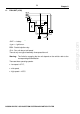
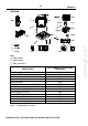
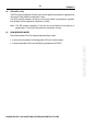
I - DIAGRAM
SDI028D
1
7
5
2
3
4
6
A
B
C
8080 4026
0004
8020
1510
1360
V1300
V4020
8007
1220
C001
1320
BSI1
Key:
A - VAN network
B - CAN network
C - Wire connection
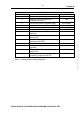
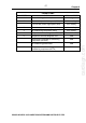
DESCRIPTION
PART NUMBER IN THE WIRING
DIAGRAMS
Automatic gearbox ECU (*) 1360
Diagnostic LED V1300
Fan unit 1510
Air conditioning compressor 8020
Instrument panel 0004
Coolant temperature warning LED V4020
Coolant temperature gauge 4026
Built-in systems interface BSI1
Central diagnostic socket C001
Injection ECU 1320
Air conditioning ECU 8080
Air conditioning pressurestat 8007
Coolant temperature sensor 1220
Note: (*) depending on version.
cardiagn.com