
User Manual

Chapter 10
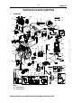
BOSCH HDI EDC 15C2 INJECTION SYSTEM AND PARTICLE FILTER
62
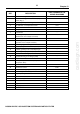
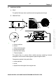
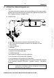
REF. DESCRIPTION
PART NUMBER IN THE
WIRING DIAGRAMS
1 Additional heating control relay BCP3
2 Additional heating (electrical resistors (2a) or
heater (2b)) (*)
8098 - 1190
3 Variable geometry turbocharger --
4 Air flowmeter / air temperature sensor 1310
5 Air filter --
6 Catalytic converter --
7 Particle filter --
8 Exhaust gas temperature sensor
(downstream of the catalytic converter)
1343
9 Differential pressure sensor 1341
10 Exhaust gas temperature sensor
(upstream of the catalytic converter)
1344
11 Turbocharging pressure regulation electrovalve 1233
12 Recycling regulation electrovalve (EGR) 1253
13 Variable geometry turbo control diaphragm --
14 Exhaust gas recycling valve (EGR) --
15 Air/water heat exchanger (inlet air heater) --
16 Coolant/exhaust gas exchanger (EGR) --
17 Inlet air heater throttle control electrovalve 1285
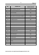
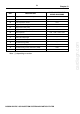
18 Atmospheric pressure sensor (incorporated into
the injection ECU)
1320
19 Injection ECU 1320
20 Heated rear screen 8120
21 Electronic stability program ECU (*) 7800
22 Automatic gearbox ECU (*) 1360
23 Trip computer (*) --
24 Electronic rev counter 4210
25 Service LED (*) --
26 Preheater LED V1150
27 Diagnostic LED V1300
28 Fuel gauge (*) --
29 Fan unit 1510
cardiagn.com