
User manual

Checking
Set all HIGH, MID, LOW and PAN controls to the mid position (12o’clock) and AUX/DSP controls fully left (-∞)
Test each channel’s gain level by pressing in the PFL (Pre-Fade Listen) switch. If any PFL switches are on, the VU meters will
display the output of the PFL channel(s) instead of the overall output.
Make the loudest expected sound through that channel and increase the GAIN control until the signal reaches the 0dB mark.
Dynamic attacks, like the strike of a drum or pluck of a string, may be allowed to go into the amber coloured LEDs (up to +7dB)
but the red LEDs (+10dB) represent clipping, which should be avoided.
Once the GAIN is set, switch off the PFL for that channel and repeat the process for all other input channels.
Test the main mix output by gradually increasing the MASTER faders and selected channel faders whilst making sound through
the channel(s) – the L + R output LED ladders should begin to show the output as it varies up and down. Output will be heard
through any connected headphones or speakers.
Operation
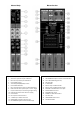
Each channel has a 3-band EQ (LOW/MID/HIGH), which can be used to balance the mix of frequencies and emphasise certain
aural characteristics in the signal. Adjust these as required, noting that and overall increase may require an equivalent reduction
of the GAIN control to compensate (otherwise clipping may occur from EQ boost).
An individual PEAK LED on each channel helps to show if any channel input is clipping.
Use the PAN control to position the channel input either to the left or right side of the stereo field. This can be useful to help
separate and define sounds within a mix but be aware that extreme settings can be counter-productive by removing the channel
from certain listening positions.
Use the AUX control to feed the correct amount of the channel signal to the AUX SEND. The combined AUX SEND level from all
channels is governed by the AUX SEND rotary control. Likewise, the AUX RETURN rotary control determines the level fed back
into the mixer via the AUX RETURN jack. Adjust AUX SEND so that its output does not overload connected equipment and
match the level brought back with the AUX RETURN control.
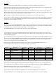
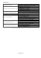
Each channel has a DSP control which feeds a portion of the signal to the internal DSP (Digital Signal Processor)
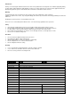
The internal DSP section can provide one of 16 internal effect types, as listed below…
Program
Effect Type
Parameter
Program
Effect Type
Parameter
1
2
Chorus
Depth
9
10
Reverb: Bright Room
Reverb time
2
Reverb: Dark Room
Reverb time
10
Delay + Reverb 1
Delay time
3
Delay
Delay time
11
Reverb: Cavern
Reverb time
4
Flanger
Rate
12
Reverb: Concert
Reverb time
5
Detune
Rate
13
Reverb: Dark Hall
Reverb time
6
Phaser
Rate
14
Reverb: Bright Hall
Reverb time
7
Rotary
Rate
15
Reverb: Cathedral
Reverb time
8
Reverb: Tunnel
Rate
16
Delay + Reverb 2
Delay time
Each effect has a particular adjustable setting which can be altered, changing the nature of the chosen effect program. These
are listed in the table above and the best setting can be found for each by experimentation with the DSP PARAMETER control.
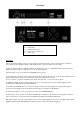
Overall DSP effect level fed to the mix is controlled via the DSP fader.
There is also a 2-TRACK fader to adjust the level of the signal fed in via the 2-TRACK RCA inputs.
Channel faders should be used to adjust the individual levels in the mix and the MAIN fader is for overall level.
Turn down MASTER levels when changing any connections or powering down the mixer to avoid speaker damage