
User guide


CSP & CSL-series User Manual
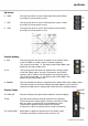
Mic/Line Input Section
Channel inputs and inserts are provided as XLR and/or 6.3mm jack sockets.
The connections for these inputs are assigned as follows.
1. MIC input Connect a balanced microphone to this XLRF input.
An unbalanced microphone can be connected provided
that +48V phantom power is not used. Wired as follows.
2. LINE input Connect balanced or unbalanced line level signals to this
6.3mm TRS jack input. Wired as follows.
3. L/MONO input For stereo channels, connect line level signals to 2 TRS jack
4. RIGHT input inputs for Left and Right. If the input is mono, only connect
to the L/MONO input, which will feed to both Left and Right.
Wired as follows.
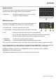
5. GAIN control This control trims the input signal to the optimum level for the channel strip circuitry.
Too low a signal level can result in a weak signal-to-noise ratio and too high can result
in overload and distortion in the signal output.
The PEAK LED next to the channel fader will give an indication of the signal level.
Ideally, the Gain rotary control should be adjusted so that the loudest passages of the
input signal (e.g. bass drum beats) will just momentarily trigger the CLIP LED.
Anything longer than a momentary flicker of the CLIP LED means that the Gain should
be reduced. Using the PFL button further down the channel strip gives a more detailed
view of the channel level on the main VU LEDs.
Balanced
Pin 1 = Ground
Pin 2 = Signal +
Pin 3 = Signal –
Unbalanced
Pin 1 = Ground
Pin 2 = Signal +
Pin 3 = Ground
Balanced
Tip = Signal +
Ring = Signal –
Sleeve = Ground
Unbalanced
Tip = Signal +
-
Sleeve = Ground
Balanced
Tip = Signal +
Ring = Signal –
Sleeve = Ground
Unbalanced
Tip = Signal +
-
Sleeve = Ground