
Operation Manual


Introduction:
Thank you for choosing a Citronic active crossover. This product has been designed to give accurate control for a multi-amplifier
sound reinforcement system. In order to achieve the best results from this equipment and avoid damage through misuse, please
read and follow these instructions and retain for future reference.
Warning:
To prevent the risk of fire or electric shock, do not expose any part of the unit to rain or moisture.
If liquids are spilled on the surface, stop using immediately, allow unit to dry out and have checked by qualified personnel before
further use.
Avoid impact, extreme pressure or heavy vibration to the unit.
There are no user serviceable parts inside the crossover – refer all servicing to qualified service personnel.
Safety
Check that the supplied mains lead is in good condition and the supply voltage is correct.
Ensure signal leads are of good condition and connected to appropriate inputs/outputs
Do not allow any foreign particles to enter the console through control apertures or connector apertures
Placement
Keep out of direct sunlight and away from heat sources.
Keep away from damp or dusty environments.
When rack-mounting, avoid placing heavy units above the unit and ensure all connectors are accessible
Cleaning
Use a soft cloth with a neutral detergent to clean the casing as required
Use a soft brush to clear debris from the control surface
Do not use strong solvents for cleaning the unit.
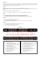
Front Panel
14. Low Cut filter: Channel B
15. Low/High - Mid/High crossover Frequency: Channel B
16. Low/High - Low/Mid crossover Frequency: Channel B
17. Low or Mid output gain: Channel B
18. Mid/High - High-mid/High crossover frequency: Ch B
19. Low or Mid output phase switch: Channel B
20. Low output gain: Channel B
21. Low output phase switch: Channel B
22. Mid or High-mid output gain: Channel B
23. Mid or High-mid output phase switch: Channel B
24. High output gain: Channel B
25. High output phase switch: Channel B
26. Power switch
1. Input gain: Channel A
2. Low Cut filter: Channel A
3. Low/High X-over Frequency: Channel A
4. Low/High - Low/Mid crossover Frequency: Channel A
5. Low/Mid - Mid/High crossover Frequency: Channel A
6. Low output gain: Channel A
7. Low output phase switch: Channel A
8. Mid or Low-mid output gain: Channel A
9. Mid or Low-mid output phase switch: Channel A
10. High output gain: Channel A
11. High output phase switch: Channel A
12. Mono/Stereo mode indicators
13. Input gain: Channel B