
Owner's manual
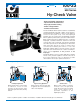


CLA-VAL
Copyright Cla-Val 2013 Printed in USA Specifications subject to change without notice.
P.O. Box 1325 • Newport Beach, CA 92659-0325 • Phone: 949-722-4800 • Fax: 949-548-5441 • E-mail: claval@cla-val.com • Website cla-val.com
©
Cla-Val Control Valves operate with maximum efficiency when mounted in horizontal piping with the main valve cover UP, however, other
positions are acceptable. Due to component size and weight of 10 inch and larger valves, installation with cover UP is advisable. We recommend
isolation valves be installed on inlet and outlet for maintenance. Adequate space above and around the valve for service personnel should be
considered essential. A regular maintenance program should be established based on the specific application data. However, we recommend a
thorough inspection be done at least once a year. Consult factory for specific recommendations.
Note: The top two flange holes on valve sizes 36 thru 48 are threaded to 1 1/2"-6 UNC.
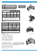
Model 100-23
EE
D
E
Inlet
DD
AA
100-23
Flanged
F
A
C
(MAX)
K
J
H
Inlet
Outlet
FF
B
(Diameter)
Dimensions
E-100-23 (R-2/2013)
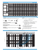
Valve Size (Inches) 3 4 6 8 10 12 14 16 18 20 24 30 36 42 48
A 150 ANSI 10.25 13.88 17.75 21.38 26.00 30.00 34.25 35.00 42.12 48.00 48.00 63.25 65.00 76.00 94.50
AA 300 ANSI 11.00 14.50 18.62 22.38 27.38 31.50 35.75 36.62 43.63 49.62 49.75 63.75 67.00 76.00 94.50
B Dia. 6.62 9.12 11.50 15.75 20.00 23.62 27.47 28.00 35.44 35.44 35.44 53.19 56.00 66.00 66.00
C Max. 7.00 8.62 11.62 15.00 17.88 21.00 20.88 25.75 25.00 31.50 31.50 43.94 54.60 61.50 61.50
D 150 ANSI — 6.94 8.88 10.69 — — — — — — — — — — —
DD 300 ANSI — 7.25 9.38 11.19 — — — — — — — — — — —
E 150 ANSI — 5.50 6.75 7.25 — — — — — — — — — — —
EE 300 ANSI — 5.81 7.25 7.75 — — — — — — — — — — —
F 150 ANSI 3.75 4.50 5.50 6.75 8.00 9.50 11.00 11.75 15.88 14.56 17.00 19.88 25.50 28.00 31.50
FF 300 ANSI 4.12 5.00 6.25 7.50 8.75 10.25 — 12.75 15.88 16.06 19.00 22.00 27.50 28.00 31.50
H NPT Body Tapping .375 .50 .75 .75 1 1 1 1 1 1 1 1 2 2 2
J NPT Cover Center Plug .50 .50 .75 .75 1 1 1.25 1.25 2 2 2 2 2 2 2
K NPT Cover Tapping .375 .50 .75 .75 1 1 1 1 1 1 1 1 2 2 2
Valve Stem Internal Thread UNF 10-32
1
⁄4-28
1
⁄4-28
3
⁄8-24
3
⁄8-24
3
⁄8-24
3
⁄8-24
3
⁄8-24
1
⁄2-20
1
⁄2-20
1
⁄2-20
3
⁄4-16
3
⁄4-16 M20 M20
Stem Travel 0.6 0.8 1.1 1.7 2.3 2.8 3.4 3.4 4.5 4.5 4.5 6.5 7.5 8.5 8.5
Approx. Ship Wt. Lbs. 45 85 195 330 625 900 1250 1380 2365 2551 2733 6500 8545 12450 13100
Valve Size (mm) 80 100 150 200 250 300 350 400 450 500 600 750 900 1000 1200
A 150 ANSI 260 353 451 543 660 762 870 889 1070 1219 1219 1607 1651 1930 2400
AA 300 ANSI 279 368 473 568 695 800 908 930 1108 1260 1263 1619 1702 1930 2400
B Dia. 168 232 292 400 508 600 698 711 900 900 900 1351 1422 1676 1676
C Max. 178 219 295 381 454 533 530 654 635 800 800 1116 1387 1562 1562
D 150 ANSI — 176 226 272
CF* CF* CF* CF* CF* CF* CF*
— — — —
DD 300 ANSI — 184 238 284
CF* CF* CF* CF* CF* CF* CF*
— — — —
E 150 ANSI — 140 171 184
CF* CF* CF* CF* CF* CF* CF*
— — — —
EE 300 ANSI — 148 184 197
CF* CF* CF* CF* CF* CF* CF*
— — — —
F 150 ANSI 95 114 140 171 203 241 279 298 403 370 432 505 648 711 800
FF 300 ANSI 105 127 159 191 222 260 — 324 403 408 483 559 699 711 800
H NPT Body Tapping .375 .50 .75 .75 1 1 1 1 1 1 1 1 2 2 2
J NPT Cover Center Plug .50 .50 .75 .75 1 1 1.25 1.25 2 2 2 2 2 2 2
K NPT Cover Tapping .375 .50 .75 .75 1 1 1 1 1 1 1 1 2 2 2
Valve Stem Internal Thread UNF 10-32
1
⁄4-28
1
⁄4-28
3
⁄8-24
3
⁄8-24
3
⁄8-24
3
⁄8-24
3
⁄8-24
1
⁄2-20
1
⁄2-20
1
⁄2-20
3
⁄4-16
3
⁄4-16 M20 M20
Stem Travel 15 20 28 43 58 71 86 86 86 114 114 165 191 216 216
Approx. Ship Wt. Kgs. 20 39 89 150 284 409 568 627 681 1157 1249 2951 3876 5647 5942
For assistance in selecting appropriate valve options or valves manufactured with special design requirements, please contact our Regional Sales Office or Factory.