ClareVision Network Video Recorder Installation Guide 4-Channel NVR with PoE Doc ID 2015-01-344 • Rev 04
Copyright © 13JAN15 Clare Controls, Inc. All rights reserved. This document may not be copied in whole or in part or otherwise reproduced without prior written consent from Clare Controls, Inc., except where specifically permitted under US and international copyright law. Trademarks The ClareVision name is a trademark of Clare Controls, Inc. Other trade names used in this document may be trademarks or registered trademarks of the manufacturers or vendors of the respective products.
Content NVR pre-installation...1 Package contents...1 NVR installation...1 Hard disk installation (optional)...2 Front panel...4 Rear panel...5 HDD storage calculation chart...6 Startup...7 Using the Setup Wizard...7 Live View...11 Adding and configuring IP cameras...11 Configuring basic parameters of IP cameras...12 PTZ control...14 PTZ settings...14 PTZ control...15 Playback...16 Instant playback by channel...16 Playback by channel...
ii ClareVision Network Video Recorder Installation Guide
NVR pre-installation This NVR is highly advanced surveillance equipment that should be installed with care. Follow these precautionary steps before the installation of the NVR. • Keep all liquids away from the NVR. • Install the NVR in a well-ventilated and dust-free area. • Ensure environmental conditions meet factory specifications. • Install a manufacturer recommended HDD.
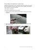
Hard disk installation (optional) Additional SATA hard disks can be installed on your NVR. Disconnect the power from the NVR before installing a hard disk drive (HDD). A factory recommended HDD should be used for this installation. Tools required: screwdriver. To install the hard disk drive into the NVR: 1. Remove the cover from the NVR by unfastening the screws on the rear and side panels. 2. Connect one end of the data cable to the motherboard of the NVR and the other end to the HDD.
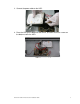
3. Connect the power cable to the HDD. 4. Place the HDD on the bottom of the device, and then fasten the screws on the bottom to affix the HDD.
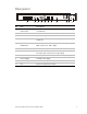
Front panel (1) (2) (3) (4) No. Name Description 1 Power POWER: The POWER LED turns green when the NVR is powered up. 2 Status READY: The LED is green when the device is running normally. STATUS: 1. The light is green when the IR remote control is enabled. 2. The light is red when the function of the composite keys (SHIFT) are used. 3. The light will not be on if one of the above conditions are not met. ALARM: When an alarm occurs, the light will turn red.
Rear panel (1) (2) (3) (4) (5) (6) (7) (8) (9) (10) (11) No. Item Description 1 Network Interfaces with PoE function The network interfaces for the cameras and provide power over Ethernet. 2 USB Connects USB disks and devices. 3 HDMI HDMI video output connector. 4 VGA DB9 connector for VGA output. Display local video output and menu. 5 AUDIO IN BNC connector for audio input. (Also for two-way audio) AUDIO OUT BNC connector for audio output.
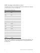
HDD storage calculation chart The following chart shows an estimate of storage space used based on recording on one channel for an hour at a fixed bit rate.
Startup Proper startup procedures are crucial to expand the life of the NVR. To start the NVR: 1. Check that the power supply is plugged in. We recommend that you use an Uninterruptible Power Supply (UPS) in conjunction with the device. 2. Press the POWER button on the rear panel. The Power LED should turn green as the unit starts. Using the Setup Wizard By default, the Setup Wizard starts once the NVR has loaded. To operate the Setup Wizard: 1.
3. Click Next on the Wizard window to enter the Login window. 4. Enter the admin password. By default, the password is “secure7” 5. To change the admin password, select the New Admin Password checkbox. Enter and confirm the new password in the given fields. 6. Click Next to enter the date and time settings window.
7. After the time settings are set, click Next to return to the Network Setup Wizard window. Note: The internal NIC IPv4 address must be on a separate subnet. 8. Click Next to enter the HDD Management window. 9. To initialize the HDD, click Init., initialization removes all the data saved in the HDD. 10. Click Next. You will enter the Adding IP Camera interface. 11. Click Search to find the online IP Camera. 12. Select the IP camera, and then click Add.
13. Click the Next button. Configure the recording for the searched IP Cameras. 14. Click Copy to copy the settings to other channels. 15. Click OK to complete the Setup Wizard.
Live View Some icons are provided on screen in Live View mode to indicate the different camera statuses. Icons appear at the top right of the screen for each channel. They show the status of the record and alarm features in the channel so that you can identify problems quickly.
To add the online cameras with same network segment: 1. Click Search to search the online cameras. 2. Select the checkboxes for the cameras to be added. 3. Click Quick Add to add the cameras. Configuring basic parameters of IP cameras After adding the IP camera, the camera information displays on the page. Configure the basic parameters of the IP camera. To configure or edit IP cameras: 1. Click the icon to edit the parameters.
2. Click Apply to save the settings, and then click OK to exit the editing interface. More parameter options: 1. Scroll to the right on the screen, and then click the Advance Set icon. 2. You can edit the network information and the password of the camera. 3. Click Apply to save the settings, and then click OK to exit the interface.
PTZ control Follow the procedure to set the parameters for the PTZ. You should configure the PTZ parameters before you set the PTZ of the camera. Before you begin, ensure the PTZ and the NVR are connected properly through the RS-485 interface. PTZ settings To set PTZ: 1. Enter the PTZ Settings interface (Menu > Camera > PTZ). 2. Choose the camera for PTZ setting next to the Camera label. 3. Enter the parameters for the PTZ camera. Note: All the parameters should be the same as the PTZ camera parameters. 4.
PTZ control To enter the PTZ panel in the Live View mode, you can press the PTZ Control button on the front panel, on the remote, or choose the PTZ Control icon .
Playback Play back the recorded files of a specific channel in the Live View menu. Instant playback by channel Choose a channel under Live View using the mouse, and then click the in the shortcut operation menu. button Note: Only files recorded during the last five minutes on the channel will be played back. Playback by channel To playback by channel: 1. Enter the Playback menu. Mouse: Right-click a channel in Live View mode and select from the menu.
Check the channel or channels if you want to switch playback to another channel or execute simultaneous playback of multiple channels. Backup Recorded files can be backed up to various devices, such as USB flash drives, USB HDDs, or a DVD writer. To back up recorded files: 1. Enter Video Export interface (Menu > Export > Normal). 2. Select the channels you want to back up, set search condition, and then click Search to enter the search result interface. 3.
Note: You can choose to export the record files and the related log files to the player. 5. Check the backup results. Choose the record file in the Export interface, and then press to check it.
Understanding camera capacity in an NVR When setting up your NVR and cameras, you may notice that some of the camera images may not display in Live View. This most often occurs when you are displaying images in 1+5 mode, or 1+7 mode because the total bit rate for all cameras is exceeding the NVR’s capacity. The actual capacity depends on the total bit rate from all the cameras. However, it is good practice to allow some headroom for machine operations, such as remote streaming.
Each channel can support a different camera, as long as they do not exceed the total bit rate limit. It is entirely possible to mix 5 MP cameras with 4CIF IP cameras, etc. Generally, 5 MP at 30 fps requires around 20 Mbps for best quality. A 4-channel NVR is currently limited to 16 Mbps. Adjusting settings Be aware of your NVR’s capacity and make adjustments, if necessary. Adjust the bit rate by lowering the resolution, frame rate, or video quality setting. To adjust the setting: 1.
Specifications Video/audio input Network Video/audio output Hard disk External interface PoE Others IP video input 4-ch Two-way audio input 1-ch, RCA (2.0 Vp-p, 1 kΩ) Incoming bandwidth 20 Mbps Output bandwidth 40 Mbps Remote connection 128 Recording resolution 5 MP/ 3 MP/ 1080 p/ UXGA/ 720p/ VGA/ 4 CIF/ DCIF/ 2 CIF/ CIF/ QCIF HDMI/VGA output 1-ch, resolution: 1920 × 1080 P/ 60 Hz, 1600 × 1200/ 60 Hz, 1280 × 1024/ 60 Hz, 1280 × 720/ 60 Hz, 1024 × 768/ 60 Hz CVBS (optional) 1-ch, BNC (1.
Regulatory information DISCLAIMER Underwriters Laboratories Inc. (UL) has not tested the performance or reliability of the security or signaling aspects of this product. UL has only tested for fire, shock or casualty hazards as outlined in UL’s Standard(s) for Safety, UL60950-1. UL Certification does not cover the performance or reliability of the security or signaling aspects of this product.
Contact information Clare Controls, Inc. 7519 Pennsylvania Ave, Suite 104 Sarasota, FL 34243 Support: 941.404.1072 Fax: 941.870.9646 http://support.clarecontrols.com www.clarecontrols.