Clare Controls IP Network Cameras User Guide Doc ID 2014-12-343 • Rev 04
Copyright © 29DEC14 Clare Controls, Inc. All rights reserved. This document may not be copied in whole or in part or otherwise reproduced without prior written consent from Clare Controls, Inc., except where specifically permitted under US and international copyright law. Trademarks and patents The Clare Controls IP Network Cameras name and logo are trademarks of Clare Controls, Inc.
Disclaimer statement “Underwriters Laboratories Inc. (“UL”) has not tested the performance or reliability of the security or signaling aspects of this product. UL has only tested for fire, shock or casualty hazards as outlined in UL’s Standard(s) for Safety, UL60950-1. UL Certification does not cover the performance or reliability of the security or signaling aspects of this product.
Content Important information...1 Limitation of liability...1 Safety warnings and cautions...2 Advisory messages...3 System requirement...4 Network connection...5 Setting the network camera over a LAN...5 Wiring over a LAN...5 Detecting and changing the IP address...6 Setting the network camera over a WAN...7 Static IP connection...7 Connecting the network camera with static IP directly...7 Dynamic IP connection...8 Connecting the network camera via a modem...8 Access to the network camera...
Network camera configuration...26 Configuring local parameters...26 Configuring time settings...27 Configuring TCP/IP settings...29 Configuring port settings...30 Configuring PPPoE settings...30 Configuring DDNS settings...31 Configuring SNMP settings...33 Configuring 802.1X settings...34 Configuring QoS settings...35 Configuring FTP settings...35 Configuring UPnP settings...36 Configuring video settings...37 Configuring audio settings...39 Configuring ROI encoding...40 Configuring image parameters...
Storage settings...62 Configuring NAS settings...62 Configuring recording schedule...63 Playback...67 Log searching...69 Others...70 Understanding camera capacity in an NVR...70 Streaming video types...70 Adjusting settings...71 Managing user accounts...71 Configuring RTSP authentication...73 Anonymous visit...73 IP address filter...74 Viewing device information...76 Maintenance...76 Rebooting the camera...76 Restoring default settings...77 Importing/exporting configuration files...77 Upgrading the system..
iv Clare Controls IP Network Camera User Guide
Important information Limitation of liability To the maximum extent permitted by applicable law, in no event will Clare Controls, Inc. be liable for any lost profits or business opportunities, loss of use, business interruption, loss of data, or any other indirect, special, incidental, or consequential damages under any theory of liability, whether based in contract, tort, negligence, product liability, or otherwise.
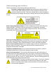
Safety warnings and cautions Please pay attention to the following warnings and cautions. Hazardous voltage may be present: Special measures and precautions must be taken when using this device. Some voltages on the device may present a hazard to the user. This device should only be used by employees from our company with knowledge and training in working with devices that contain live circuits. Power supply hazardous voltage: AC mains voltages are present within the power supply assembly.
Perchlorate material: Special handling may apply. See www.dtsc.ca.gov/hazardouswaste/perchlorate. This notice is required by California Code of Regulations, Title 22, Division 4.5, and Chapter 33: Best Management Practices for Perchlorate Materials. This device includes a battery which contains perchlorate material. Thermal and mechanical injury: Some components such as heat sinks, power regulators, and processors may be hot. Care should be taken to avoid contact with these components.
Cautions Before using the camera, make sure the power supply voltage is correct. Do not drop or subject the camera to physical shock. Do not touch the sensor modules with your fingers. If cleaning is necessary, use a clean cloth with a bit of ethanol and wipe it gently. If the camera will not be used for an extended period, put the lens cap on to protect the sensor from dirt. Do not aim the camera lens at strong light such as the sun or an incandescent lamp.
Network connection If you want to set the network camera via a LAN (Local Area Network), refer to “Setting the network camera over a LAN” on page 5. If you want to set the network camera via a WAN (Wide Area Network), refer to “Setting the network camera over a WAN” on page 7. Setting the network camera over a LAN To view and configure the camera via LAN, you must connect the network camera in the same subnet as your computer. Install the SADP software to search for and change the IP of the network camera.
Detecting and changing the IP address You need the IP address to visit the network camera. To detect and change the IP address: 1. To get the IP address, you can choose one of the following methods: Use SADP, a software tool which can automatically detect the online network cameras in a LAN. List the device information including IP address, subnet mask, port number, device serial number, device version, etc., shown in Figure 3. Use the client software to list all online devices.
Setting the network camera over a WAN This section explains how to connect the network camera to a WAN with a static IP or a dynamic IP. Static IP connection Apply a static IP from an ISP (Internet Service Provider). With the static IP address, you can connect the network camera via a router or connect it to a WAN directly. To connect the network camera via a router: 1. Connect the network camera to the router. 2. Assign the LAN IP address, subnet mask, and gateway. 3. Save the static IP in the router. 4.
Dynamic IP connection Apply a dynamic IP from an ISP. With the dynamic IP address, you can connect the network camera to a modem or a router. To connect the network camera via a router 1. Connect the network camera to the router. 2. In the camera, assign a LAN IP address, subnet mask, and gateway. 3. In the router, set the PPPoE user name and password. 4. Set port mapping, e.g., 80, 8000, 8200 and the 554 ports. The steps for port mapping vary based on router.
Figure 7: Normal domain name resolution Steps: 1. Obtain and apply a domain name from a domain name provider. 2. Configure the DDNS settings in the DDNS settings interface of the network camera, and then click Save. 3. When prompted, reboot for the settings to take effect. 4. Configure the DDNS settings of the camera via the applied domain name. Figure 8: Private domain name resolution Steps: 1. Install and run the IP server software on a computer with a static IP. 2.
Access to the network camera Accessing by web browsers Accessing the network camera through a web browser lets you view the camera feed and configure the cameras settings. To access the camera by web browsers: 1. Open the web browser. 2. In the address field, enter the IP address of the network camera (e.g., 192.168.1.250), and then press Enter. This brings you to the login interface. 3. Enter the user name and password, and then click Login.
4. Install the plug-in, if prompted, and follow the installation prompts before viewing the live video and operating the camera. 5. Click OK. 6. Click Next.
7. Click Finish. Note: You may need to close the web browser to install the plug-in. After installing the plug-in, reopen the web browser and log in.
Wi-Fi settings You do not need to use cables when connecting to the wireless network. Note: This chapter is only applicable for the cameras with a Wi-Fi module built-in, like the Clare Controls 1.3 MP Budget Mini-Dome Camera with Wi-Fi. Configuring Wi-Fi connection in manage and ad-hoc modes A wireless network must be configured. To configure a wireless connection in Manage Mode: 1. Enter the Wi-Fi configuration interface. Configuration > Camera Configuration > Network > Wi-Fi 2.
Wireless connection in ad-hoc mode If you choose the Ad-Hoc mode, you do not need to connect the wireless camera via a router. The camera broadcast the wireless signal. Connect the camera directly to the PC with a network cable. To configure a wireless connection in ad-hoc mode: 1. Choose Ad-Hoc mode. 2. Customize the SSID for the camera. 3. Choose the Security Mode of the wireless connection. 4. Enable the wireless connection function for your PC. 5.
Security mode Figure 9: Security Mode Options You select the Security Mode; not-encrypted, WEP, WPA-personal, WPA-enterprise, WPA2-personal, and WPA2-enterprise. Figure 10: WEP Mode Authentication - Select Open or Shared Key System Authentication, depending on the method used by the access point. Not all access points have this option. Key Length - This sets the length of the key used for the wireless encryption, 64 or 128 bit. The encryption key length can sometimes be shown as 40/64 and 104/128.
WPA-personal and WPA2-personal mode: Enter the required pre-shared key for the access point, a hexadecimal number or a passphrase. Figure 11: Wi-Fi key 1 WPA- enterprise and WPA2-enterprise mode: Choose the type of client/server authentication being used by the access point: EAP-TLS or EAP-PEAP.
EAP-TLS Identity - Enter the user ID to present to the network. Private key password – Enter the password for your user ID. EAPOL version - Select the version used (1 or 2) in your access point. CA certificates - Upload a CA certificate to present to the access point for authentication. EAP-PEAP: User Name - Enter the user name to present to the network. Password - Enter the password of the network. PEAP Version - Select the PEAP version used at the access point.
PBC mode: PBC (Push-Button-Configuration) allows the user to push a button, on both the Access Point and the new wireless client device for configuration. To enable the PBC function: 1. Select the Enable WPS checkbox. 2. Choose the connection mode as PBC. Note: The Access Points much each support PBC mode. 3. Check the Wi-Fi router for a WPS button. Push the button, and the indicator near the button starts flashing. This means the WPS function is enabled.
2. Select Use router Pin code. 3. If the PIN is generated from the router, enter the PIN in the Router PIN code field. 4. Click Connect. - or You can generate a PIN code using the camera. The expiration time for the PIN code is 120 seconds. 5. Click Generate. 6. Enter the code to the router in the PIN Code field.
IP property settings for wireless network connection The default IP address of the wireless network interface controller is 192.168.1.64. When you connect the wireless network you can change the default IP. To change the default IP: 1. Enter the TCP/IP configuration interface. Configuration > Camera Configuration > Network > TCP/IP 2. Set Select NIC as wlan. 3. Customize the IPv4 address, the IPv4 Subnet Mask, the IPv4 Default Gateway, and the Multicast Address. The setting use the same process as the LAN.
Live View Live View page The live video page lets you view live video, capture images, utilize PTZ control, set/call presets, and configure the video parameters. Log in the network camera to enter the live view page, or click Live View on the menu bar of the main page. Figure 14: Live View page with descriptions Menu bar: Click each tab to enter the Live View, Playback, Log, and Configuration page. Live View window: Displays the live video. Toolbar: Operations of the live view page, e.g.
Starting live view Click on the toolbar to start the live view of the camera. Figure 15: Live View toolbar Table 1: Description of the toolbar Icon Description This starts/stops the live view. This manually captures the pictures displayed in live view, and then save it them as JPEG files. This manually starts/stops recording. This turns audio on, adjust volume, and mutes the device. This turns on/off the microphone. This turns on/off the PTZ.
Operating PTZ control In the live view interface, use the PTZ control buttons to realize pan/tilt/zoom control of the camera. To realize PTZ control, the camera connected to the network must support the PTZ function or a pan/tilt unit must be installed on the camera. Properly set the PTZ parameters on RS-485 settings page. PTZ control panel To control PTZ: 1. On the live view page, click to show the PTZ control panel and to hide it. 2. Click the direction buttons to control the pan/tilt movements. 3.
Setting/calling a preset Setting a preset allows you to switch the camera to a preset position, without having to readjust manually. The preset can be selected at any time or be set for certain events. To set a Preset: 1. In the PTZ control panel, select a preset number from the list. 2. Use the PTZ control buttons to move the lens to the desired position. Pan the camera to the right or left. Tilt the camera up or down. Zoom in or out. Refocus the lens. 3.
Configuring Live View parameters You can select the stream type and change the image size on the live view page. To select the stream and adjust the image size: 1. Click the Main Stream, Third Stream, or Sub Stream tab under the menu bar of the live view interface to set the stream type. 2. Click each tab original, or auto fix.
Network camera configuration Configuring local parameters The local configuration refers to the parameters of the live view, record files, and captured pictures. To configure local parameters: 1. Enter the Local Configuration interface. Configuration > Local Configuration 2. Configure the following settings: Live View parameters: Set the protocol type and live view performance. o Protocol Type: TCP, UDP, MULTICAST, and HTTP are selectable.
Record File settings: Set the saving path of the recorded video files. Valid for the record files you recorded with the web browser. o Record File Size: Set the packed size of the manually recorded and downloaded video files to 256 M, 512 M or 1 G. o Save record files to: Set the saving path for the manually recorded video files. o Save downloaded files to: Set the saving path for the downloaded video files in playback mode.
2. Select the Time Zone. 3. Select the checkbox to enable the NTP function. 4. Configure the following settings. Server Address: IP address of the NTP server. NTP Port: Port of the NTP server. Interval: The time interval between the two synchronizing actions of the NTP. Note: If the camera is connected to a public network, use an NTP server that has a time synchronization function.
Configuring TCP/IP settings Configure the TCP/IP settings to operate the camera over the network. The camera supports both the IPv4 and IPv6, both versions may be configured simultaneously without conflicting each other. At least one IP needs to be configured. To configure the TCP/IP settings: 1. Enter TCP/IP Settings interface. Configuration > Camera Configuration > Network > TCP/IP 2.
Configuring port settings You can set the port numbers of the camera, e.g., HTTP port, RTSP port, and HTTPS port. To configure port settings: 1. Enter the Port Settings interface. Configuration > Camera Configuration > Network > Port 2. Set the HTTP port, RTSP port and HTTPS port of the camera. HTTP Port: The default port number is 80, it can be changed to a port range from 1024 to 65535. RTSP Port: The default port number is 554.
2. Select the Enable PPPoE checkbox to enable this feature. 3. Enter User Name, Password, and Confirm the password for PPPoE access. Note: The User Name and Password is assigned by your ISP. 4. Click Save. 5. When prompted, reboot for the settings to take effect. Configuring DDNS settings If your camera is set to use PPPoE as its default network connection, you can use the Dynamic DNS (DDNS) for network access. Registration on the DDNS server is required before configuring the DDNS settings of the camera.
To configure IP server: 1. Enter the Server Address of the IP Server. 2. Click Save. Note: For the IP Server, you have to apply a static IP, subnet mask, gateway, and the preferred DNS from the ISP. The Server Address should be entered with the static IP address of the computer that runs the IP Server software. Note: For the US and Canada area, you can enter 173.200.91.74 as the server address. To configure HiDDNS: 1. Choose the DDNS Type as HiDDNS. 2. Enter the Server Address www.hiddns.com. 3.
Configuring SNMP settings You can set the SNMP function to get the camera status, parameters, alarm-related information, and manage the camera remotely when it is connected to the network. Before setting the SNMP, download the SNMP software and receive the camera information via SNMP port. By setting the Trap Address, the camera can send the alarm event and exception messages to the surveillance center. Note: The SNMP version you select should match the SNMP software.
2. Select the corresponding version checkbox to enable the feature. , , 3. Configure the SNMP settings. Note: The settings of the SNMP software must match the settings you configured here. 4. Click Save. 5. When prompted, reboot for the settings to take effect. Configuring 802.1X settings The IEEE 802.1X standard is supported by the network cameras. When the feature is enabled, the camera data is secured. User authentication is needed when connecting the camera to a network protected by the IEEE 802.1X.
Configuring QoS settings QoS (Quality of Service) can help solve network delay and congestion by configuring the priority of the data sent. To configure QoS settings: 1. Enter the QoS Settings interface. Configuration > Camera Configuration > Network > QoS 2. Configure the QoS settings, including video/audio DSCP, event/alarm DSCP, and Management DSCP. 3. The valid value range of the DSCP is 0 to 63. The larger the DSCP value, the higher the priority is.
2. Enter the user name and password required for logging into the FTP server in the corresponding fields. 3. In the Directory Structure field, select the root directory, parent directory, or child directory. When the parent directory is selected, you have the option to use the Device Name, Device Number, or Device IP for the name of the directory. When the Child Directory is selected, you can use the Camera Name or Camera No. as the name of the directory. 4.
2. Select the Enable UPnP checkbox. This enables the Friendly Name field. 3. In the Friendly Name field, enter the name of the device. 4. From the Port Mapping Mode drop-down, choose one of the following: Auto for port mapping with the default port numbers. - or Manual for port mapping with the customized port numbers. 5. Click Save. Configuring video settings Customizing the video settings allows for better quality images based on the custom needs of that video stream. To configure video settings: 1.
2. In the Stream Type field, select Main Stream (normal), Sub-Stream, or Third Stream. Note: Main Stream is optimal for recording and live viewing with good bandwidth. Sub Stream and Third Stream can be used for live viewing with limited bandwidth. 3. You can customize the following parameters for the selected Stream. Video type: Set the stream type to video stream, or video and audio composite stream. The audio signal will be recorded only when the Video Type is Video and Audio.
Profile: Basic profile, Main Profile, and High Profile are selectable for coding. I Frame interval: Set the I-Frame interval from 1 to 400. SVC: Scalable video coding (SVC) is an extension of the H.264 /AVC standard. The technology encodes the video signal with layers, a basic layer and several enhanced layers. It adapts to the network condition to transfer different video streams. For example, when the bandwidth is limited, only the basic layer data is encoded and transferred.
Configuring ROI encoding ROI stands for the region of interest. ROI encoding lets you discriminate the ROI and background information in comparison. This means that the technology assigns more encoding resources to the region of interest to increase the quality of the ROI view. Note: Only certain cameras support this function. To configure ROI encoding: 1. Enter the ROI settings interface. Configuration > Camera Configuration > Video/Audio > ROI 2. Draw the region of interest on the image.
Overexposure prevention: Enable or disable the function in this field. Exposure time: Value ranges from 1/3 to 1/100,000 s. Adjust it according to the light condition. Iris mode: Auto and Manual are selectable. Auto iris Level: If you choose the auto iris mode, you can set the auto iris level. Video standard: 50 Hz and 60 Hz are selectable. Choose according to the different video standards; normally 50 Hz for the PAL standard and 60 Hz for the NTSC standard.
BLC area: BLC area is the sense of the light intensity; Close, Up, Down, Left, Right, and Center are selectable. White balance: The below figure shows the white balance options. Select according to the real condition. For example, if there is a fluorescent lamp in the surveillance scene, select the white balance type as Fluorescent Lamp. Digital noise reduction: Close, Normal, and Expert Mode are selectable. Noise reduction level: Adjusts the noise reduction level.
Configuring OSD Settings You can customize the camera name and time displayed on the screen. To configure OSD settings: 1. Enter the OSD Settings interface. Configuration > Camera Configuration > Image > OSD Settings 2. Select the corresponding checkbox to select the display of camera name, date, or week if required. 3. In the Camera Name field, enter the name of the camera. 4. Set the Time Format, Date Format, Display Mode, and OSD Size from the dropdown lists. 5.
Configuring text overlay settings You can customize the text overlay. To configure text overlay settings: 1. Enter the Text Overlay Settings interface. Configuration > Camera Configuration > Image > Text Overlay 2. Select the box in front of textbox to enable the on-screen display. 3. Input the characters in the textbox. 4. Use the mouse to click and drag the red text frame in the live view window to adjust the text overlay position. 5. Click Save. Note: You can configure up to four text overlays.
Configuring privacy mask Privacy mask lets you cover certain areas on the live video to prevent zones in the surveillance area from being viewed or recorded. To configure privacy mask 1. Enter the Privacy Mask Settings interface. Configuration > Camera Configuration > Image > Privacy Mask 2. Select the box of Enable Privacy Mask check box to enable this function. 3. Click Draw Area. 4. Click and drag the mouse in the live video window to draw the mask area. Note: You are allowed 4 areas on the same image.
Configuring picture overlay Picture overlay lets you overlay a picture on the image. To configure picture overlay: 1. Enter the Picture Overlay Settings interface. Configuration > Camera Configuration > Image > Picture Overlay 2. Click Browse to add a picture from your PC. 3. Click Upload to upload it. 4. Slect the checkbox Enable Picture Overlay to enable this function. 5. Set the X Coordinate and Y Coordinate values for the location of the picture on the image. 6.
Configuring and handling alarms This section explains the configuration of the network camera to respond to alarm events, including motion detection, external alarm input, video loss, video tampering, and exception. These events can trigger the alarm actions to Notify Surveillance Center, Send Email, etc. For example, when an external alarm is triggered, the network camera sends a notification to an email address.
Arming schedule for motion detection You can set the arming schedule for motion detection. Figure 16: Arming schedule screen To set the arming schedule for motion detection: 1. Click Edit. 2. Choose the day. 3. Set the time. 4. After you set the arming schedule, you can copy the schedule to other days. 5. Click OK to save the settings. Note: The time of each period cannot be overlapped. Four periods can be configured each day.
Set the alarm actions for motion detection. You can specify the linkage method when an event occurs. Figure 18: Linkage method selection To set the alarm actions: 1. Select the checkbox for a linkage method. Audible warning, notify surveillance center, send email, upload to FTP, and trigger channel are selectable. Audible warning: This triggers the audible warning locally. Notify surveillance center: This sends an exception or alarm signal to remote management software when an event occurs.
2. Select the Enable Video Tampering checkbox to enable the tamper-proof detection. 3. Set the tamper-proof area. 4. Click Edit. 5. Select the checkbox to select the linkage method taken for video tampering. Audible warning, notify surveillance center, and send email are selectable. 6. Click Save. Handling exception The exception type can be HDD full, HDD error, network disconnected, IP address conflicted, or illegal login to the cameras. To configure handling exceptions: 1.
Email sending triggered by alarm The system can be configured to send an Email notification to all designated receivers if an alarm event is detected – for example, motion detection event, video loss, video tampering, etc. Note: Before using the Email function, configure the DNS server settings. Go to Configuration > Network > TCP/IP. To send email triggered by an alarm: 1. In TCP/IP, set the IPv4 /IPv6 Address, IPv4 /IPv6 Subnet Mask, IPv4 /IPv6 Default Gateway, and the Preferred DDNS Server. 2.
Attached image: Select the checkbox Attached Image if you want to send the emails with attached alarm images. Interval: The interval refers to the time between the actions of sending attached pictures. Authentication (optional): If your email server requires authentication, select this checkbox to use authentication to log in to this server and enter the login user name and password. Receiver: The name of the user to be notified. Receiver’s address: The email address of user to be notified. 4. Click Save.
To upload event-triggered snapshots to FTP: 1. Configure the FTP settings and select the Upload Picture checkbox in the FTP Settings interface. 2. Select the Upload to FTP checkbox in the Motion Detection Settings. 3. Select the Enable Event-triggered Snapshot checkbox. Configuring other alarms This section is for cameras that support external wireless alarms (access control alarm), and manual alarm by remote control.
Arming or disarming the camera This section if for supported cameras only. Follow the steps below to configure all-day arming for the camera with the wireless alarm, PIR alarm, motion detection, video tampering, etc. Notes The emergency alarm is enabled and armed by default. The arming and disarming function can be set by the remote control. To arm the camera: 1. Enter the Remote Control interface. Configuration > Camera Configuration > System > Remote Control 2.
Configuring PTZ This section explains the PTZ functions of the network camera. This enables the pan/tilt/zoom control of the camera. To realize PTZ control, the camera connected to the network must support the PTZ function, or a pan/tilt unit must be installed on the camera. Properly set the PTZ parameters in the Camera Configuration settings page. Configuring the basic PTZ settings The Basic settings lets you change basic parameters, speeds, and OSD. To configure the basic settings interface: 1.
Auto Scene Speed: Select an option 1 through 40. Max. Tilt-angle: Select either -5 to 90, -4 to 90, -3 to 90, -2 to 90, -1 to 90, and 0 to 90. Auto Flip: Select either On or Off. Zooming Speed: Select 1, 2, or 3. 3. In the PTZ OSD fields, customize the following. Zoom Status: Select Always Open, Always Closed, 2 seconds, 5 seconds, and 10 seconds. PT Status: Select Always Open, Always Closed, 2 seconds, 5 seconds, and 10 seconds.
2. Select the Enable Limit checkbox to enable this function 3. Select from the Limit Type drop-down. Manual Stops, movement being controlled by user. – or – Scan Stops, is automatic movement. 4. Customize the position and movement on the left. You also have the option to select a preset. 5. Click Save. Configuring the initial PTZ position The Initial Position lets you set an initial starting position for the camera. To configure the initial position: 1. Enter the Initial Position settings interface.
Configuring the PTZ park action The Park Actions lets you stop the camera. To configure the park action: 1. Enter the Park Action settings interface. Configuration > Camera Configuration > PTZ > Park Action 2. Select the Enable Park Action checkbox to enable this function. 3. In the Park Time field, enter a time in seconds for the park time. 4. Customize the Action Type drop-down from the following options. Auto Scan: This scans automatically. Frame Scan: This scans by image frame.
2. Select the Enable Privacy Mask checkbox to enable this function. 3. Click Draw Area. 4. Click and drag the mouse in the live video window to draw the mask area. 5. The Privacy Mask List lets you customize the name, type, if enable, and add or delete an area. Note: You are allowed two areas on the same image. 6. Click Stop Drawing to finish drawing, or click Clear All to clear all of the areas you set without saving them. 7. Click Save.
2. Set a second amount in the Park Time field. 3. Click Edit Tasks to change the day, task type, start time, and end time. Note: You can copy the tasks to certain days of the week. 4. Click Save.
Clearing a PTZ configuration The Clear Configuration settings lets you clear other settings individually, by selection of more than one, or all at the same time. To clear the configuration: 1. Enter the Clear Configuration settings interface. Configuration > Camera Configuration > PTZ > Clear Configuration 2. Select the checkboxes of the desired areas. 3. Click Save. Configuring the prioritize PTZ Prioritizing the PTZ lets you prioritize where PTZ control comes from. To configure the prioritize PTZ: 1.
Storage settings To configure record settings, make sure that you have a network storage device in the network, or have the SD card inserted in your camera. Configuring NAS settings The network disk should be available within the network and be properly configured to store the record and log files. To add the network disk: 1. Enter the NAS (Network-Attached Storage) Settings interface. Configuration > Camera Configuration > Storage > NAS 2.
2. If the status of the disk is uninitialized, select the corresponding checkbox to select the disk, then click Format to start initializing the disk. 3. When initialization is completed, the status of disk will become Normal. Notes Up to eight NAS disks can be connected to the camera. Refer to the NAS disk instillation to initialize and use the SD card. Configuring recording schedule There are two kinds of recordings for the cameras: manual recording and scheduled recording.
2. Select the Enable Record Schedule checkbox to enable scheduled recording. 3. Set the recording parameters of the camera. Pre-record: This is the time you set to start recording before the scheduled time for the event. For example, if an alarm triggers recording at 10:00, and the pre-record time is set as 5 seconds, the camera starts to record at 9:59:55. The Pre-record time can be configured as No Pre-record, 5 seconds, 10 seconds, 15 seconds, 20 seconds, 25 seconds, 30 seconds, or not limited.
Choose the day to set the record schedule. Set all-day record or segment record: 1. If you want to configure the all-day recording, select the All Day checkbox. If you want to record in different time sections, select the Customize checkbox. Set the Start Time and End Time. Note: The time of each segment cannot be overlapped. You can configure up to four segments. 2. Select a Record Type.
Record Triggered by Motion & Alarm: If you select Motion and Alarm, the video will be recorded when the motion and alarm are triggered at the same time. Configure the recording schedule and the settings on the Motion Detection and Alarm Input Settings interfaces. Record Triggered by PIR Alarm: If you select PIR Alarm, the video will be recorded when the PIR alarm is detected.
Playback View the recorded video files stored in the network disks or SD cards. To configure playback: 1. Click Playback on the menu bar to enter the playback interface. 2. Select the date and click Search. 3. Click to play the video files found on this date. Use the toolbar on the bottom of Playback interface to control play.
Table 3: Description of the Playback toolbar Icon Operation Play Pause Stop Speed down Speed up Playback by single frame Capture a picture Start/Stop clipping video files Audio on and adjust volume/Mute Download video files Download captured pictures Note: You can choose the file path locally for downloaded playback video files and pictures in Local Configuration interface.
Log searching The operation, alarm, exception, and information of the camera can be stored in log files. You can export the log files on demand. Before searching, configure the network storage for the camera, or insert an SD card in the camera. To search logs: 1. Click Log on the menu bar to enter the log searching interface. 2. Set the log search conditions to specify the search, including the Major Type, Minor Type, Start Time, and End Time. 3. Click Search.
Others Understanding camera capacity in an NVR When setting up your NVR and cameras, you may notice that some of the camera images may not display in Live View. This most often occurs when you are displaying images in 1+5 mode, or 1+7 mode because the total bit rate for all cameras is exceeding the NVR’s capacity. The actual capacity depends on the total bit rate from all the cameras. However, it is good practice to allow some headroom for machine operations, such as remote streaming.
Generally, 5 MP at 30 fps requires around 20 Mbps for best quality. A 4-channel NVR is currently limited to 16 Mbps. Adjusting settings Be aware of your NVR’s capacity and make adjustments, if necessary. Adjust the bit rate by lowering the resolution, frame rate, or video quality setting. To adjust the setting: 1. Enter the Live View settings interface. 2. Adjust the Resolution, Frame Rate, and Video Quality settings. Managing user accounts Enter the User Management interface.
To modify a user: 1. Click to select the user from the list and click Modify. 2. Modify the User Name, Level, or Password. 3. In the Basic Permission field and Camera Configuration field, you can select or clear the permissions. 4. Click OK to finish the user modification. To delete a user: 1. Click the user name you want to delete and click Delete. 2. Click OK on the pop-up dialogue box to delete the user.
Configuring RTSP authentication You can specifically secure the stream data of live view. To configure RTSL authentication: 1. Enter the RTSP Authentication interface. Configuration > Camera Configuration > Security > RTSP Authentication 2. Set the Authentication type to basic or disable it in the drop-down list. Note: If you disable the RTSP authentication, anyone can access the video stream by the RTSP protocol using the IP address. 3. Click Save.
2. Set the Anonymous Visit permission in the drop-down list to enable or disable the anonymous visit option. 3. Click Save. The Anonymous checkbox displays the next time you log in. 4. Select the Anonymous checkbox, and then click Login. IP address filter This function makes it possible for access control. To configure the IP address filter: 1. Enter the IP Address Filter interface. Configuration > Camera Configuration > Security > IP Address Filter 2. Select the Enable IP Address Filter checkbox. 3.
4. Select either Forbidden or Allowed. 5. Set the IP Address Filter list. To add an IP address: 1. Click Add to add an IP. 2. Enter the IP Adreess. 3. Click OK to finish adding. To modify an IP address: 1. Click an IP address from the filter list and click Modify. 2. Modify the IP address in the text filed. 3. Click OK to finish modifying. To delete an IP address: 1. Click an IP address from the filter list and click Delete. To delete all IP addresses: 1. Click Clear to delete all of the IP addrsses. 2.
Viewing device information Enter the Device Information interface. Configuration > Camera Configuration > System > Device Information In the Device Information interface, you can edit the device name. Other information of the network camera, such as Model, Serial No., Firmware Version, Encoding Version, Number of Channels, Number of HDDs, Number of Alarm Input, and Number of Alarm Output are displayed. The information cannot be changed in this menu.
Restoring default settings To restore default settings: 1. Enter the Maintenance interface. Configuration > Camera Configuration > System > Maintenance 2. Click Restore or Default to restore the default settings. Note: When restoring the default settings, the IP address returns to the default. Importing/exporting configuration files To import and export configuration files: 1. Enter the Maintenance interface.
2. Click Browse to select the local configuration file, and then click Import to start importing the configuration files. Note: You need to reboot the camera after importing a configuration file. 3. Click Export and set the saving path to save the configuration file in local storage. Upgrading the system To upgrade the system: 1. Enter the Maintenance interface. Configuration > Camera Configuration > System > Maintenance 2.
Note: If you want to connect the camera by the RS-232 port, the parameters of the RS-232 must match the parameters configured here. 2. Click Save. RS-485 settings The RS-485 serial port is used to control the PTZ of the camera. Configure the PTZ parameters before you control the PTZ unit. To configure RS-485 settings: 1. Enter RS-485 Port Setting interface. Configuration > Advanced Configuration > System > RS485 2. Set the RS-485 parameters and click Save to save the settings.
Appendix 1 SADP software introduction Description of SADP V 2.0 SADP (Search Active Devices Protocol) is a user-friendly, installation-free online device search tool. It searches for the active online devices in your subnet and displays their information. Using this software, you can modify the basic network information of the devices. Note: SADP is a Windows only product.
Search online devices manually Click Refresh to refresh the online device list manually. The new devices will be added to the list. Note: You can click information. or on each column heading to change the order of the You can click to expand the device table and hide the network parameter panel on the right side, or click to show the network parameter panel. Modify network parameters To modify network parameters: 1.
Appendix 2 Port mapping The following settings are for a TP-LINK router (TL-R410). The settings vary depending on the router model. To set port mapping: 1. Select the WAN Connection Type, as shown below. 2. Set the LAN parameters of the router as in the following figure, including the IP address and subnet mask settings. 3. Set the port mapping in the virtual severs of Forwarding. By default, the camera uses port 80, 8000, 554 and 8200.
As the settings mentioned above, map the port 80, 8000, 554 and 8200 for the network camera at 192.168.1.23 To map the ports: 1. Map the port 81, 8001, 555 and 8201 for the network camera at 192.168.1.24. 2. Enable ALL or TCP protocols. 3. Select the Enable checkbox and click Save. Note: The ports of the network camera cannot conflict with other ports. For example, the web management port of the router is 80. Change the camera port if it is the same as the management port.