
User's Manual

IDSmart UHF Security Gate User Manual
© Copyright 2014 ClarIDy Solutions, Inc. All rights reserved. 8/40
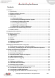
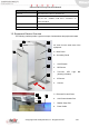
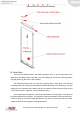
* Ethernet Port and Power outlet could be located at the inner side or outer side of the door
panel
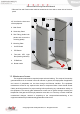
45° view from the inner area
of the equipment
A. Main Panel
B. Secondary Panel
D. Slot Fitting (Holds both
panels and connect the
mounting plates)
E. Mounting Plate
1. On/Off Switch
2. PIR Sensor
3. Two-color LED Light
Bar (Warning Indicator)
9. IR Reflector
10. Buzzer outlet
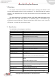
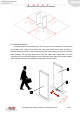
1.3. Maintenance Access
The equipment maintenance required proper tools and training. The scope of the security
gate maintenance is not covered in this user manual. In general, the deployment of application
and control of peripherals can be done through the Ethernet interface. The equipment
maintenance access is only required when there is component failure. Users should consult
Claridy technical personnel for proper training before performing any maintenance activity on
the equipment. The security gate maintenance access can be gained through removing the
lampshade of the gate and the arcylic protective cover with a no.4 hex key or wretch. Note that
unauthorized changes, removal or tampering to the component/structure/wiring of the
equipment makes the provided warranty/guarantee null and void.
A
D
3
2
9
B
E
10
1
C*