INTRODUCTION The Clarion APX200.2 and APX400.2 are full-featured two-channel amplifiers. incorporating the following features: • Full frequency response with low distrotion and exceptional signal to noise performance • Advanced circuit design that features bridgeable and mixed mode operation for use in various systems, including those with satellite speakers and/or subwoofers • Variable high-pass/low-pass electronic crossover with a 12dB per octave slope and full adjustable range (from 55Hz to 5.
DESCRIPTION The Clarion APX200.2 and APX400.2 two-channel amplifiers provide 2x70 watts and 2x110 watts of power into a 4 ohm load and 2x110 watts and 2x190 watts of power into a 2 ohm load. These full featured models are an excellent choice for a variety of car audio sound system configurations. The APX200.2 and APX400.2 use an unregulated MOSFET power supply for superior control of output wattage. A toroid-coil transformer yields maximum power transfer with minimum heat loss.
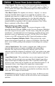
• Gain Control - This allows you to set the nominal operating level of the amplifier. The amplifier’s range, 250mV to 2.5V for RCA inputs or 500mV to 5V for speaker level inputs, can accommodate input levels from virtually any brand of source unit. • Bass Boost Control- The amplifier also features a “high-Q” (i.e. narrow frequency band) Bass Boost circuit. It acts much like an equlaizer, with adjustable gain (from 0 to +18dB) fixed at 45Hz.
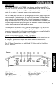
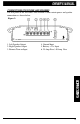
CONNECTIONS FOR POWER AND SPEAKERS The rear panel of the APX200.2 and APX400.2 both contain power and speaker connections as shown below. Figure 2- 1. Left Speaker Output 2. Right Speaker Output 3. Remote Turn-on Input 4. Ground Input 5. Battery + 12v Input 6.
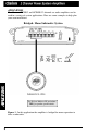
APPLICATIONS The Clarion APX200.2 and APX400.2 2-channel car audio amplifiers can be used in a variety of system applications. Here are some examples to help plan your own installation. Bridged- Mono Subwoofer System Set X-Over Mode to LP and adjust FREQ to speaker specifications. Figure 3 - In this application the amplifier is bridged for mono operation to drive a subwoofer.
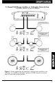
2-Channel Full-Range, Satellite, or Subwoofer Stereo System (Set INPUT SELECT Switch to STEREO) Set X-Over Mode as shown. Set X-Over Mode as shown; adjust FREQ to speaker specifications. Set X-Over Mode as shown; adjust FREQ to speaker specifications. Figure 4 - In this application, the amplifier is used in stereo and drives two full-range (or satellite or subwoofer) speakers. NOTE: A passive crossover must be used with satellite speakers.
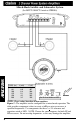
Mixed-Mode Satellite and Subwoofer System (Set INPUT SELECT Switch to STEREO) FREQ (hz) L (mH) C (uF) 80 100 125 150 200 8.0 6.4 5.1 4.2 3.2 497 398 318 265 199 Set X-Over Mode to OFF. NOTE: Chart values based on 4 ohm speakers. Figure 5 - The amplifier can be configured for a mixed-mode operation. The table provides component values to create a 6dB per octave crossover at specified frequencies. Use components that have a + 5% tolerance and capacitors rated at 100V.
INSTALLATION This section lists Mounting and Wiring Precautions for installing a Clarion APX200.2 or APX400.2. Combined with the experience of a professional installer, these safeguards provide enough detail to successfully complete an installation. If you do not have the necessary skills, do not install the amplifier yourself. Instead, see your authorized Clarion dealer for installation recommendations. MOUNTING PRECAUTIONS Although the Clarion APX200.2 and APX400.
4. A secure clean ground connection is critical to the performance of your Clarion amplifier. Use the shortest ground wire possible snd securely connect to the car chassis to minimize resistance and avoid noise problems. 5. Add an external fuse on the amplifier’s positive (+) power lead and connect it as close as possible to the vehicle’s (+) battery terminal. Use a rating that equals the total current consumption at full output of all amplifiers in the system.
Figure 6. - Electrical connections for the APX200.2 or the APX400.
SETTING THE GAIN After completing the installation, follow these steps to set the Gain Control and then perform the Final System Checks. 1. Turn the Gain Control all the way counter-clockwise. 2. Turn the vehicle’s Ignition Switch to the ON position. Then turn the ON/OFF Switch on the source units to the ON position. Set all Tone or Equalization Controls to “flat” positions and turn Loudness off. 3. Play a CD or Tape and set the Volume Control at 75% of full level.
FINAL SYSTEM CHECKS 1. Start the engine and turn on the source unit. After a two-second delay, slowly increase the Volume Control and listen to the audio. If you hear any noise, static, distortion or no sound at all, check the connections, and also refer to Troubleshooting. Depending on your system design, the levels may become quite loud even at low Volume Control settings. Until you get an “audio feel” of the system’s power, use care when adjusting controls. 2.
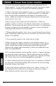
Problem Distorted audio. Solution Gain is not set properly, or damaged speaker cones. Review Setting Gain; inspect each speaker cone for signs of damage (i.e. frozen cone, burning smell, etc.) Problem Audio lacks punch. Solution Speakers wired incorrectly, which causes cancellation of bass frequencies. Check polarity of wires from amplifier to each speaker as defined by the system design. Problem Amplifier fuse keeps blowing. Solution Incorrect wiring or short circuit.
NOTES 15
661 W. Redondo Beach Blvd. Gardena, CA 90247 1-800-GO-CLARION www.clarion-usa.com APX2CH-10 Rev.