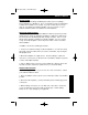
apx201.
apx201.qxd 12/5/01 12:57 PM Page 2 2 Channel Power System Amplifier TABLE OF CONTENTS Introduction . . . . . . . . . . . . . . . . . . . . . . . . . . . . . . . . Description . . . . . . . . . . . . . . . . . . . . . . . . . . . . . . . . . Input Connections and Audio Controls . . . . . . . . . . . . Connections for Power and Speakers . . . . . . . . . . . . . Applications . . . . . . . . . . . . . . . . . . . . . . . . . . . . . . . . Installation . . . . . . . . . . . . . . . . . . . . . . . . . . . . .
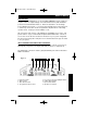
apx201.qxd 12/5/01 12:57 PM Page 3 Owner’s Owner’sManual Manual DESCRIPTION The APX201.2 and APX401.2 use an unregulated MOSFET power supply for superior control of output wattage. A toroid-coil transformer yields maximum power transfer with minimal heat loss. Extensive attention to circuit design keeps AM RFI at low levels, so you won’t hear unwanted noise when the level is cranked up. Protection circuits safeguard the amplifier when overheating, speaker shorts, or improper load conditions occur.
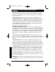
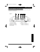
apx201.qxd 12/5/01 12:57 PM Page 4 2 Channel Power System Amplifier • Gain Control - This allows you to set the nominal operating level of the amplifier. The amplifier’s range, 250mV to 2.5V for RCA inputs or 500mV to 5V for speaker level inputs, can accommodate input levels from virtually any brand of source unit. • Bass Boost Control- The amplifier also features a “high-Q” (i.e. narrow frequency band) Bass Boost circuit.
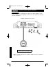
apx201.qxd 12/5/01 12:57 PM Page 5 Owner’s Manual CONNECTIONS FOR POWER AND SPEAKERS The rear panel of the APX201.2 and APX401.2 contains power and speaker connections as shown below. Figure 2- 1. 2. 3. 4. 1 Left Speaker Output Right Speaker Output Remote Turn-on Input Ground Input 2 3 4 5 6 5. Battery +12V Input 6. 25 Amp Fuse (APX201.2) 40 Amp Fuse (APX401.
apx201.qxd 12/5/01 12:57 PM Page 6 2 Channel Power System Amplifier APPLICATIONS The Clarion APX201.2 and APX401.2 2-channel car audio amplifiers can be used in a variety of system applications. Here are some examples to help plan your own installation. Bridged- Mono Subwoofer System Subwoofer 4 Ohms Set X-Over Mode to LP and adjust FREQ to speaker specifications. Figure 3 - In this application the amplifier is bridged for mono operation to drive a subwoofer.
apx201.qxd 12/5/01 12:57 PM Page 7 Owner’s Manual 2-Channel Full-Range, Satellite, or Subwoofer Stereo System Set X-Over Mode as shown Set X-Over Mode as shown; adjust FREQ to speaker specifications. Set X-Over Mode as shown; adjust FREQ to speaker specifications. Figure 4 - In this application, the amplifier is used in stereo and drives two full-range (or satellite or subwoofer) speakers. NOTE: A passive crossover must be used with satellite speakers.
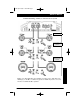
apx201.qxd 12/5/01 12:57 PM Page 8 2 Channel Power System Amplifier Mixed-Mode Satellite and Subwoofer System FREQ (hz) 80 100 125 150 200 L (mH) 8.0 6.4 5.1 4.2 3.2 C (uF) 497 398 Set X-Over Mode to OFF NOTE: Chart values based on 4 ohm speakers. Figure 5 - The amplifier can be configured for a mixed-mode operation. The table provides component values to create a 6dB per octave crossover at specified frequencies. Use components that have a + 5% tolerance and capacitors rated at 100V.
apx201.qxd 12/5/01 12:57 PM Page 9 Owner’s Manual INSTALLATION This section lists Mounting and Wiring Precautions prior to installing a Clarion APX201.2 or APX401.2. These safeguards provide enough detail to complete the installation successfully. If you do not have the necessary skills, do not attempt to install the amplifier yourself. Instead, see your authorized Clarion dealer for installation recommendations. MOUNTING PRECAUTIONS Although the Clarion APX201.2 and APX401.
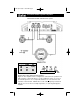
apx201.qxd 12/5/01 12:57 PM Page 10 2 Channel Power System Amplifier 4. A secure, clean ground connection is critical to the performance of your Clarion amplifier. Use the shortest ground wire possible and securely connect to the car chassis to minimize resistance and avoid noise problems. Besure to clean off any paint, prior to making this connection. 5. Add an external fuse on the amplifier’s positive (+) power lead and connect it as close as possible to the vehicle’s (+) battery terminal.
apx201.qxd 12/5/01 12:57 PM Page 11 Owner’s Manual Figure 6. - Electrical connections for the APX201.2 or the APX401.
apx201.qxd 12/5/01 12:57 PM Page 12 2 Channel Power System Amplifier SETTING THE GAIN After completing the installation, follow these steps to set the Gain Control and then perform the Final System Checks. 1. Turn the Gain Control all the way counter-clockwise. 2. Turn the vehicle’s Ignition Switch to the ON position. Then turn the ON/OFF Switch on the source units to the ON position. Set all Tone or Equalization Controls to “flat” positions and turn Loudness off. 3.
apx201.qxd 12/5/01 12:57 PM Page 13 Owner’s Manual FINAL SYSTEM CHECKS 1. Start the engine and turn on the source unit. After a two-second delay, slowly increase the Volume Control and listen to the audio. If you hear any noise, static, distortion or no sound at all, check the connections, and also refer to Troubleshooting. Depending on your system design, the levels may become quite loud even at low Volume Control settings.
apx201.qxd 12/5/01 12:57 PM Page 14 2 Channel Power System Amplifier Problem Distorted audio. Solution Gain is not set properly, or damaged speaker cones. Review Setting Gain; inspect each speaker cone for signs of damage (i.e. frozen cone, burning smell, etc.) Problem Audio lacks punch. Solution Speakers wired incorrectly, which causes cancellation of bass frequencies. Check polarity of wires from amplifier to each speaker as defined by the system design.
apx201.qxd 12/5/01 12:57 PM Page 15 Owner’s Manual PRODUCT SPECS APX201.2 Frequency Response Signal Noise Ratio THD Input Sensitivity Low Level Input Sensitivity Speaker Level Max. Power Output Cont. Power Output 2-Ohm Stereo Output Bridged Power Dimensions Current Consumption at output @ max power 20Hz ~ 20kHz >100db .05% all channels driven 250mV ~ 2.5 V 500mV - 5V 220w (110 x 2) 100w (50w x 2) @.08% THD 110 x 2 @ .05% THD 220 x 1 @ .05% THD 2 1/8” H x 8 1/4” W x 9” L 28A @ 235 Watts APX401.
apx201.qxd 12/5/01 12:57 PM Page 16 WARRANTY INFORMATION This product is warranted against all defects in material workmanship for a period of one year from the date of original purchase. Clarion ProAudio products except for speakers are covered by a two year warranty when installed by an authorized Clarion dealer. The conditions of this warranty and the extent of responsibility of Clarion Corporation under this warranty are as follows: 1.