APX600.5 Power System Amplifier INTRODUCTION The Clarion APX600.5 is a full-featured five-channel amplifier. It comes with the following features: • Full frequency response with low distortion and exceptional signal to noise performance • Advanced circuit design for flexibility and operation of 5, 4 or 3 channel systems • Independent front high pass & rear high / low / bandpass electronic crossovers, each with a 12dB per octave slope and full adjustment range (55Hz to 5.
OWNER'S MANUAL DESCRIPTION The Clarion APX600.5 five channel car audio amplifier is an excellent choice for creating a variety of multi-channel sound systems. It features built-in system design flexibility that allows you to create a 3, 4, or 5 channel amplifier system with a flip of a switch. You can also configure the front, rear and subwoofer amplifier sections to drive a set of satellite speakers and/or subwoofer.
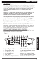
APX600.5 Power System Amplifier • Gold-Plated RCA Input Connectors -The Input Connections are GoldPlated RCA Jacks and are labeled as Right Front, Left Front, Right Rear, Left Rear, Right Sub and Left Sub. • Gain Controls - The Gain Controls provide a wide adjustment range to accommodate output levels from any brand of source unit. Seperate Front, Rear, and Sub Gain Controls allow you to set the nominal operating level of the amplifier. The amplifier ranges are 250mV to 2.
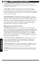
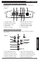
OWNER'S MANUAL CONNECTIONS FOR POWER AND SPEAKERS The rear panel of the APX600.5 contains power and speaker connections as shown below. Figure 2- 1 2 3 4 5 Left Rear Speaker Output Right Rear Speaker Output Remote Turn-on Input Ground Input Battery + 12v Input 6 7 8 9 0 Remote Sub Level Connector Left Front Speaker Output Right Front Speaker Output Subwoofer Speaker Output + 12 V Cap Input CROSSOVER SELECTION SWITCHES The bottom panel of the APX600.
APX600.
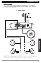
OWNER'S MANUAL APPLICATIONS The Clarion APX600.5 multi-channel car audio amplifier can be used in a variety of system applications. Enclosed are some example system layouts to help plan your own installation. 3-Channel Mode R Full Range L Satellite R Satellite 2-way Passive Crossover APPLICATIONS APPLICATIONS L Full Range 2-way Passive Crossover Figure 5 - In this application, the APX600.5 is used as a 3-channel amplifier to drive two full-range or Satellite speakers in stereo plus a subwoofer.
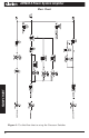
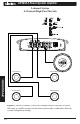
APX600.5 Power System Amplifier 5-channel System 2-Channels High-Pass, 2-Channels Band-Pass Plus Sub R Satellite 2-way Passive Crossover L Mid Bass 2-way Passive Crossover R Mid Bass Figure 6 - In this 5-channel system, the APX600.5 drives a pair of stereo satellites for the front and a pair of stereo mid bass for the rear plus a sub. Note the system configuration settings.
OWNER'S MANUAL L Tweeter R Tweeter L Midrange R Midrange APPLICATIONS APPLICATIONS 5-channel System 2-Channels High-Pass, 2-Channels Band-Pass Plus Sub Figure 7 - The APX600.5 can also be used to drive a pair of tweeters, midrange, and a subwoofer. Note the system configuration settings.
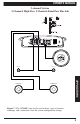
APX600.5 Power System Amplifier LF Full Range RF Full Range LR Full Range RR Full Range Figure 8 - In this 5-channel system, the APX600.5 drives two pairs of stereo full range or satellite speakers for the front and rear plus a subwoofer. Note the system configuration settings.
OWNER'S OWNER'S MANUAL MANUAL INSTALLATION This section lists Mounting and Wiring Precautions for installing the Clarion APX600.5. These safeguards provide enough detail to successfully complete an installation. If you do not have the necessary skills, Clarion recommends consulting your authorized Clarion dealer for installation. MOUNTING PRECAUTIONS Although the Clarion APX600.
APX600.5 Power System Amplifier 6. Refer to Figure 9 when making electrical connections. Connect the amplifier’s positive (+) lead via a fuse directly to the positive (+) terminal on the battery. Do not connect this wire to the car’s fuse panel. Use red-insulated 8-gauge (or larger) wire for the amplifier’s positive (+) power lead and the same-gauge black insulated wire for the ground. 7. When replacing the amplifier’s fuse, always use one having the same current rating.
OWNER'S MANUAL SETTING THE GAIN After completing the installation, follow these steps to set the Gain Control to tune the amplifier. Then perform the Final System Checks. 1. Turn the Gain Control all the way counter-clockwise. 2. Turn the vehicle’s Ignition Switch to the ON position. Then turn the ON/OFF Switch on the source units to the ON position. Set all Tone or Equalization Controls to “flat” positions and turn Loudness off.
APX600.5 Power System Amplifier FINAL SYSTEM CHECK 1. Start the engine and turn on the source unit. After a two-second delay, slowly increase the Volume Control and listen to the audio. If you hear any noise, static, distortion or no sound at all, check the connections, and also refer to Troubleshooting. Depending on your system design, the levels may become quite loud even at low Volume Control settings. Until you get an “audio feel” of the system’s power, use care when adjusting controls. 2.
OWNER'S MANUAL Problem Audio lacks punch. Solution Speakers wired incorrectly, which causes cancellation of bass frequencies. Check polarity of wires from amplifier to each speaker as defined by the system design. Problem Amplifier fuse keeps blowing. Solution Incorrect wiring or short circuit. Review Installation and check all wiring connections. Problem Whining or ticking noise in the audio with engine on. Solution Amplifier is picking up alternator noise or radiated noise.
661 W. Redondo Beach Blvd. Gardena, CA 90247 1-800-GO-CLARION www.clarion-usa.com APX600.5-10 Rev.