Owner’s manual & Installation manual Mode d’emploi et manuel d’installation Manual de usuario y Manual de instalación CM1624TB CM1624TS 6.5” (165MM) 2-WAY MARINE TOWER SPEAKERS HAUT-PARLEURS TOUR MARINE BIDIRECTIONNELS , 6,5 PO (165 MM) ALTAVOCES TORRE MARINO DE 2 VÍAS DE 6.
English CLARION PRODUCT REGISTRATION INFORMATION For USA and Canada only www.clarion.com Dear Customer: Owner’s Manual Congratulations on your purchase of a Clarion marine product. We are confident that you’ll enjoy your Clarion experience. There are many benefits to register your product. We invite you to visit our web site at www.clarion.com to register your Clarion product. We have made product registration simple with our easy to use website. The registration form is short and easy to complete.
MODEL • • • • • • • • • • • • • • TYPE 6.5” (165mm) 2-Way Marine Tower Speakers POWER HANDLING 80W Continuous Power Owner’s Manual CM1624TB (Black) CM1624TS (Silver) English 1. FEATURES 200 Watts music peak power 80 Watts continuous power 6.5” (165mm) IMPP Woofer Cone 1” (25mm) PEI Dome Tweeter Built-In RGB LED Illumination Carbon Fiber Spoke Design 360 Degree Swivel Bar Clamp and Surface Mount Bar mount adjustable to fit 1.5”, 1.75”, 2”, 2.5”, 2.
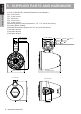
English 3. SUPPLIED PARTS AND HARDWARE Owner’s Manual (1) Pair of CM1624TB or CM1624TS Marine Tower Speakers (4) 1.5” Bar Inserts (4) 1.75” Bar Inserts (4) 2” Bar Inserts (4) 2.5” Bar Inserts (4) 2.75” Bar Inserts (4) Mounting Spacer Inserts (Required for 1.5”, 1.75” and 2” Bar Inserts) (2) Surface Mount Gaskets (4) M6 Hex Bolts 60mm (Required for 2.5” and 2.75” Bar Inserts) (1) M4 Allen Wrench (1) M5 Allen Wrench (1) M6 Allen Wrench 1.92” (48.7mm) 4.29” (109mm) 1.77” (44.9mm) 11.13” (282.8mm) [ 6.
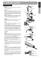
English 4. INSTALLATION Bar Mount Installation M6 Allen Wrench STEP 2: Using the supplied M6 Allen wrench, remove the M6 bolts that hold the upper clamp onto the base clamp of the tower speakers. Based upon the diameter of the tower bar, select the inserts that provides the best fit. NOTE: If using the 2.5” or 2.75” inserts, you will need to use the M6 Hex Bolt (60mm) and remove the default Mounting Spacer Inserts. Owner’s Manual STEP 1: Remove tower speakers and all the hardware from the packaging.
English 4. INSTALLATION Owner’s Manual STEP 6: Before connecting the speaker wires, please make sure you are using the correct rubber insert that best fits the tower bar being mounted to. Connect the tower speaker wires to a length of speaker wire that will be long enough to connect to the source device.
English 4. INSTALLATION Surface Mount Installation Owner’s Manual STEP 1: Remove tower speakers and all the hardware from the packaging. M4 Allen Wrench STEP 2: Using supplied M4 Allen wrench, loosen the base clamp hex head shaft bolts on the left and right side. STEP 3: Begin by pulling mount assembly out of base clamp while feeding the cable through the mount hole to create a gap between base and surface mount parts.
English 4. INSTALLATION Owner’s Manual STEP 7: Using a 1/2” drill bit, make the 1/8” pilot hole a 1/2” hole to allow a little adjustment when the tower speakers are mounted. This will help in the event of heavy vibration so the wires do not get pinched. Once the 1/2” hole has been drilled, please de-burr the hole so there are not any sharp edges that can damage the speaker wires. To help prevent wire damage, please use a rubber or plastic hole grommet.
English 5. SPECIFICATIONS GENERAL SPEC: Owner’s Manual Woofer Size: 6.
Français ENREGISTREMENT DU PRODUIT CLARION Pour les États-Unis et le Canada seulement www.clarion.com Cher client, Mode d’emploi Nous vous félicitons d’avoir fait l’acquisition d’un produit marin Clarion. Nous sommes convaincus qu’il vous apportera entière satisfaction. Vous bénéficiez d’une foule d'avantages en enregistrant votre produit. Nous vous invitons donc à visiter notre site Web à www.clarion.com pour enregistrer votre produit Clarion.
• • • • • • TYPE CM1624TB CM1624TS Haut-Parleurs Tour Marine Bidirectionnels, 6,5 Po (165 Mm) PUISSANCE ADMISSIBLE Puissance continue 80 W Mode d’emploi • • • • • • • • MODÈLE Français 1.
1.92” (48.7mm) 4.29” (109mm) 69.9mm / 63.5mm / 44.5mm / 38.1mm [ 2.75” / 2.5” / 2” / 1.75” / 1.5” 1.77” (44.9mm) 11.13” (282.
Français 4. INSTALLATION Installation de la barre de montage M6 Allen Clé ÉTAPE 2: À l’aide de la clé Allen M6 fournie, retirez les boulons M6 mm qui maintiennent la bride supérieure sur la bride de base des haut-parleurs pour tour. En fonction du diamètre du tube de la tour, sélectionnez parmi les trois espaceurs en caoutchouc fournis celui qui est le plus adapté.
Français 4. INSTALLATION Mode d’emploi Une fois le trou de 1/2 po percé, veuillez ébavurer le trou afin qu’il ne reste pas de bords métalliques coupants pouvant endommager les fils de haut-parleur. Pour éviter d’endommager les fils, veuillez utiliser un passe-fil en caoutchouc ou en plastique. ÉTAPE 6: Avant de brancher les fils du haut-parleur, vérifiez que vous utilisez bien l’espaceur en caoutchouc approprié qui s’adapte le mieux au tube de la tour où il est monté.
Français 4. INSTALLATION Installation du montage en surface ÉTAPE 2: À l’aide de la clé Allen M4, desserrer les boulons d’arbre de la tête à six pans de la bride de blocage sur les côtés droit et gauche.
Français 4. INSTALLATION Mode d’emploi ÉTAPE 7: À l’aide d’une mèche de 1/2 po, agrandissez le trou pilote de 1/8 po à 1/2 po pour permettre des petits réglages une fois les haut-parleurs tour installés. En cas de fortes vibrations, ceci Une fois le trou de 1/2 po percé, veuillez métalliques coupants pouvant endommager les caoutchouc ou en plastique. ÉTAPE 8: longue pour le raccorder à un dispositif source.
Français 5. SPÉCIFICATIONS TECHNIQUES SPÉCIFICATIONS GÉNÉRALES: Mode d’emploi Taille de Woofer: 6.
Español INFORMACIÓN SOBRE EL REGISTRO DE PRODUCTOS CLARION Para Estados Unidos y Canadá solamente www.clarion.com Manual de usuario Estimado cliente: Reciba nuestras felicitaciones por su compra de un producto marino de Clarion. Estamos seguros de que disfrutará de la experiencia Clarion. Podrá disfrutar de infinidad de ventajas si registra su producto. Por ello, lo invitamos a visitar nuestro sitio web en www.clarion.com para registrar su producto Clarion.
MODELO • • • • • • • • • • • • • • Altavoces Torre Marino De 2 Vías De 6.5” (165MM) REQUISITOS DE POTENCIA Potencia continua 80 W Manual de usuario CM1624TB CM1624TS TIPO Español 1. CARACTERÍSTICAS Potencia máxima de música 200 W Potencia continua 80 W Cono de woofer IMPP de 6.
1.92” (48.7mm) 4.29” (109mm) 69.9mm / 63.5mm / 44.5mm / 38.1mm [ 2.75” / 2.5” / 2” / 1.75” / 1.5” 1.77” (44.9mm) 11.13” (282.8mm) Manual de usuario (1) Par de altavoces de torre marina CM1624TB o CM1624TS (4) Pieza de barra de 1.5” (4) Pieza de barra de 1.75” (4) Pieza de barra de 2” (4) Pieza de barra de 2.5” (4) Pieza de barra de 2.75” (4) Piezas de espaciadores de montaje (requeridas para insertos de barra de 1.5 “, 1.
Español 4. INSTALACIÓN Instalación de montura de barra M6 Allen llave PASO 2: Con la llave Allen M6 suministrada, retire los pernos M6 que sujetan la abrazadera superior en la abrazadera de la base de los parlantes de la torre. Basado en el diámetro de la barra de la torre, seleccione las inserciones que brindan el mejor ajuste. NOTA: Si utiliza las piezas de 2.5” o 2.75”, necesitará usar el perno Hex M6 (60 mm) Manual de usuario PASO 1: Retire los altavoces de torre y todos los accesorios del embalaje.
Español 4. INSTALACIÓN Manual de usuario cables no se presionen si hay una vibración fuerte. Una vez que se ha taladrado el agujero de 1/2 pulgada, desbarbe el agujero para retirar cualquier borde metálico afilado que pueda dañar los cables de los altavoces. Para ayudar a prevenir que los cables se dañen, utilice aisladores de plástico o caucho para los agujeros.
Español 4. INSTALACIÓN Instalación de montura de superficie PASO 2: Usando la llave Allen M4 que se proporciona, afloje los pernos del eje del cabezal hex de la abrazadera base en los costados izquierdo y derecho. Manual de usuario PASO 1: Retire los altavoces de torre y todos los accesorios del embalaje.
Español 4. INSTALACIÓN PASO 7: Manual de usuario pequeño ajuste cuando los parlantes de la torre estén montados. Esto ayudará en caso de fuertes vibraciones para que los cables no queden atrapados. bles del parlante. Para ayudar a evitar daños en los cables, utilice un ojal de goma o plástico. PASO 8: Conectar los alambres del altavoz de torre a un cientemente largo para conectarse al dispositivo fuente.
Español 5. ESPECIFICACIONES ESPECIFICACIONES GENERALES: Manual de usuario Tamaño del altavoz de graves: 6.
Clarion Corporation of America All Rights Reserved.