
Product Manual


English
Owner’s Manual
CM1624TB / CM1624TS
8
4. INSTALLATION
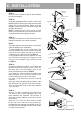
STEP 7:
Using a 1/2” drill bit, make the 1/8” pilot hole a
1/2” hole to allow a little adjustment when the
tower speakers are mounted. This will help in
the event of heavy vibration so the wires do not
get pinched.
Once the 1/2” hole has been drilled, please
de-burr the hole so there are not any sharp ed-
ges that can damage the speaker wires. To help
prevent wire damage, please use a rubber or
plastic hole grommet.
STEP 8:
Connect the tower speaker wires to a length of
speaker wire that will be long enough to connect
to the source device. If the speaker will be wired
through a hole, begin feeding the wiring into the
hole so that the surface mount can be aligned
then skip to STEP 10. If surface mounting the
wiring, proceed to STEP 9.
STEP 9:
If surface mounting the wiring, place surface
mount bracket in desired area and drill pilot ho-
les for bolts. Once pilot holes are drilled, attach
surface mount gasket to surface mount brac-
ket and slide surface mount up wire towards
speaker, leaving only enough space to attach
mount to surface. Feed cabling through side of
surface mount.
STEP 10:
If passing cables through the hole, attach
surface mount gasket to surface mount bracket
and begin fastening surface mount to surface.
Once
completed, feed
remaining wiring through
surface and insert mount end into speaker.
STEP 11:
Tighten the hex head shift bolts after rotating the
speaker to desired position.
NOTE:
Blue Loctite is highly recommended when
installing the hex head bolts.
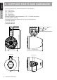
M4 Allen
Wrench
Red (-)
Green (-)
Blue (-)
Black (+)
Black (-)
Red (+)
LED Wiring
Speaker Wiring