
User's Manual

HOW TO INSTALL
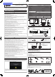
■
How to attach the receiver
•
Be sure to use the specifi ed screws when attaching the receiver. Use of other screws
may result in malfunction.
1.
Please install the receiver at stable position according to the following diagram.
!
Antenna
Rotate the antenna and fix
securely to the receiver.
7
Self tapping screw
(M5 mm x 16 mm)
5
Mounting Bracket
7
Self tapping screw
(M5 mm x 16 mm)
6
Hexagon head bolts
with built-in washer
(M5 mm x 8 mm)
6
Hexagon head bolts
with built-in washer
(M5 mm x 8 mm)
117 mm
45 mm
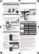
■
How to mount the camera with transmitter
•
Never swing the camera by the cable or pull the cable. Doing so may impair the
camera's watertightness or break the cable, resulting in malfunction.
•
Avoid mounting the camera where the lens will be exposed to dirt (mud splashes,
exhaust fumes, etc.).
1.
To prevent camera shake, make a hole in a rigid panel and
mount the camera as shown in the fi gure below. If the panel
is not rigid enough, carry out appropriate reinforcement.
2.
After connecting the cables, adjust the mounting angle of the
camera so that the rear bumper or back end of the vehicle
appears in the monitor.
●
Be sure to use the supplied screws to mount the
camera.
●
If any screws are lost when mounting the camera, be
sure to use hexagon head bolts with built-in washer (M3
mm x 8 mm). Do not under any circumstances use
screws that are longer than this. To ensure watertight-
ness, the screws in the camera case have a bag
structure. Use of long screws may damage the screw
thread and camera case, compromising watertightness.
WARNING
45 mm
@
Gasket
!
Antenna
Rotate the antenna and fix securely
to the camera with transmitter.
0
Mounting bracket
$
Hexagon head bolts
with built-in washer (M5 mm x 8 mm)
#
Hexagon head bolts
with built-in washer (M3 mm x 8 mm)
#
Hexagon head bolts with built-in washer (M3 mm x 8 mm)
%
Flanged nuts (M5 mm)
Vehicle side : 5.5 mm hole (Two places)
PAIRING
When using the system for the fi rst time, the camera must be paired with the receiver. Please
follow the instructions below for the pairing process.
Press [pairing switch button] : Move the cursor
Press [pairing switch button] for at least 3 seconds : Enter or start pairing
1.
Turn on the power.
→The [Clarion] welcoming screen appears
and then the screen changes in sequence.
2.
When the [Connecting] screen
appears, press the [pairing switch
button for at least 3 seconds.
→The [Searching] screen appears.
3.
The system is searching for a
compatible camera. When
searching is finished, the pairing
selection screen appears.
4.
Move the cursor to the camera
number you want to pair and
press the [pairing switch button]
for at least 3 seconds.
→The selected camera is connected and the
camera screen appears.
5.
If there is no problem with the
displayed camera image, point
the cursor to [OK] and press the
pairing switch button for at least 3
seconds.
→[OK] disappears from the screen and only
the camera image is displayed. Pairing is
completed.
Repeat Search
Check that the camera is turned on
and the antenna is connected. Point
the cursor to [ Search again ] and
press the pairing button for at least
3 seconds.
→Searching starts again.
The camera you
want to pair appears
on the pairing
selection screen
The camera you
want to pair does not
appear on the pairing
selection screen
The pairing selection
screen is not
displayed.
(No compatible
camera was found)
Advice
• You cannot pair an already paired
camera with another receiver.
• Once paired, the pairing information is
saved when the power is turned off.
• If repeated searching fails to find the
device you want to pair, it may be due
to poor radio wave reception. Replace
the antenna on the receiver with the
optional long antenna and try again.
Advice
• If the camera you want to pair does not
appear on the pairing selection screen
or if the pairing selection screen is not
displayed, follow the steps on the right
to repeat the search.
• If multiple camera numbers appear
and you do not know which to choose,
select each number in turn to find the
right one.
Advice
• If the wrong image is displayed, point
the cursor to [Cancel] and press the
pairing switch button for at least 3
seconds.
→Searching starts again and the
Searching screen appears.
WIRING AND CONNECTIONS
•
When the power cable (red) of the transmitter is connected to the ACC line, connect the
illumination signal (orange/white) from the receiver to the ACC line along with the ACC
signal (red).
•
If there is no ACC power for the transmitter, connect the transmitter's ACC to the
illumination circuit. At the same time, be sure to connect the illumination signal from the
receiver to the illumination circuit. In this case, the camera image is displayed only when
the driver turns on the illumination.
•
To prevent short-circuiting, check the connections again before connecting the battery.
RedBlack
Red
Orange
with white stripe
Purple
with white stripe
Black
ACC+
Connect to a positive power supply that can be turned on and
off with the ignition key.
Illumination
Connect to a positive power supply where the power is supplied
by turning the parking lights on.
Reverse
Connect to the positive circuit of the reverse light. This circuit
will have +12V/24V while in reverse gear.
Ground (Negative)
Connect to chassis ground.
ACC+ / Parking light
Connect to the positive power supply that can be turned on and off
with the ignition key, or to the positive parking light circuit.
NOTE: The parking lights would need to be on in order for the
camera to work and the camera image will be ready to display all
the time.
Ground (Negative)
Connect to the metal part of the vehicle.
●
Do not connect the power cable (red)
of either the transmitter or the receiver
to the +B line (permanent power
supply) as this may lead to a flat battery.
●
Disconnect the negative terminal of the
battery before connecting the cables.
Failure to do so may lead to electric
shock or injury due to short-circuit. It
may also lead
to damage to
the system
components
due to
short-circuit.
WARNING
External monitor
(sold separately)
Example of monitor
combination
Pairing
Switch
Camera
with transmitter
(CC-3500)
Receiver
(EE-2178)
TROUBLE SHOOTING
The following situations may not be malfunctions. Check once more before requesting repairs.
Symptom Cause Remedy
There is no image (Nothing appears
on the monitor)
The receiver is not connected cor-
rectly
Check the receiver’s connections and connect the receiver cor-
rectly
There is no image (“Connecting…”
is continuously displayed on the
monitor)
The camera is not connected cor-
rectly
Check the camera’s connections and connect the camera cor-
rectly
The surrounding radio wave signal
strength is weak
Move to a different place and check if the image appears
The radio wave reception of the
camera is poor
Change the position of the antenna on the receiver or replace with
the optional long antenna and check again.
There is no paired camera around Press the pairing switch button for at least 3 seconds to complete
pairing.
The image cuts out (“The video has
been stopped” appears)
The surrounding radio wave signal
strength is weak
Move to a different place and check if the image appears
The radio wave reception of the
camera is poor
Change the position of the antenna on the receiver or replace with
the optional long antenna and check again.
Communication has been discon-
nected appears on the monitor
The camera has been disconnected Depending on the state of the surrounding radio waves, the cam-
era is disconnected. Reconnection is automatic.
The camera you want to pair does
not appear on the pairing selection
screen
The camera is not connected cor-
rectly
Check the camera’s connections and connect the camera cor-
rectly
The surrounding radio wave signal
strength is weak
Move to a different place and check if the image appears
The radio wave reception of the
camera is poor
Change the position of the antenna on the receiver or replace with
the optional long antenna and check again.
The camera you want to pair has
been paired with another receiver.
Turn off the receiver to which the camera you want to pair is con-
nected and wait a while (30 seconds) before pairing again.
The button has been pressed for
more than 10 seconds. appears
The pairing switch button has been
pressed for more than 10 seconds
Check that there is nothing on top of the pairing switch button
pressing it down, and then press the pairing button once to return
to the original screen.
The pairing switch button does not
respond when pressed
The pairing switch button is not con-
nected correctly
Check the pairing switch button’s connections and connect the
button correctly.
OTHER
● IC Number :419C-EE2178, 419C-CC3500
● FCC CAUTION:
Changes or modifications not express.
● This transmitter must not be co-located or operated in conjunction with any other antenna or transmitter.
● This device complies with Part 15 of FCC Rules and Industry Canada licence-exempt RSS standard(s). Operation is subject to the following two
conditions: (1) this device may not cause interference, and (2) this device must accept any interference, including interference that may cause
undesired operation of this device.
● Le présent appareil est conforme aux la partie 15 des règles de la FCC et CNR d'Industrie Canada applicables aux appareils radio exempts de
licence. L'exploitation est autorisée aux deux conditions suivantes : (1) l'appareil ne doit pas produire de brouillage, et (2) l'utilisateur de l'appareil
doit accepter tout brouillage radioélectrique subi, même si le brouillage est susceptible d'en compromettre le fonctionnement.
● This equipment complies with FCC/IC radiation exposure limits set forth for an uncontrolled environment and meets the FCC radio frequency (RF)
Exposure Guidelines and RFF-102 of the IC radio frequency (RF) Exposure rules. This equipment should be installed in center of dashboard and
operated keeping the radiator at least 20cm or more away from person's body (excluding extremities: hands, wrists, feet and ankles).
● Cet équipement est conforme aux limites d’exposition aux rayonnements éoncés pour un environnement non contrôéet respecte les rèles
d’exposition aux fréuences radioéectriques (RF) CNR-102 de l’IC. Cet éuipement doit êre installéet utiliséen gardant une distance de 20 cm ou
plus entre le dispositif rayonnant et le corps (à l’exception des extréité : mains, poignets, pieds et chevilles).
● Under Industry Canada regulations, this radio transmitter may only operate using an antenna of a type and maximum(or lesser) gain approved for
the transmitter by Industry Canada. To reduce potential radio interference to other users, the antenna type and its gain should be so chosen that
the equivalent isotropically radiated power (e.i.r.p.) is not more than that necessary for successful communication.
● Conformément à la réglementation d'Industrie Canada, le présent émetteur radio peut fonctionner avec une antenne d'un type et d'un gain
maximal (ou inférieur) approuvé pour l'émetteur par Industrie Canada. Dans le but de réduire les risques de brouillage radioélectrique à l'intention
des autres utilisateurs, il faut choisir le type d'antenne et son gain de sorte que la puissance isotrope rayonnée équivalente (p.i.r.e.) ne dépasse
pas l'intensité nécessaire à l'établissement d'une communication satisfaisante.
● This radio transmitter (IC :419C-EE2178 ,419C-CC3500) has been approved by Industry Canada to operate with the antenna types listed below
with the maximum permissible gain and required antenna impedance for each antenna type indicated. Antenna types not included in this list,
having a gain greater than the maximum gain indicated for that type, are strictly prohibited for use with this device.
● Le présent émetteur radio (IC:419C-EE2178 ,419C-CC3500) a été approuvé par Industrie Canada pour fonctionner avec les types d'antenne
énumérés ci-dessous et ayant un gain admissible maximal et l'impédance requise pour chaque type d'antenne. Les types d'antenne non inclus
dans cette liste, ou dont le gain est supérieur au gain maximal indiqué, sont strictement interdits pour l'exploitation de l'émetteur.
• Antenna type:Dipole Gain:2.4dBi Model:CC3500,EE2178
• Antenna type:Dipole Gain:2dBi (5dBi + Cable Loss 3dB) Model:CC3500,EE2178
• Antenna type:Dipole Gain:1dBi (7dBi + Cable Loss 6dB) Model:CC3500
● This equipment has been tested and found to comply with the limits, pursuant to Part 15 of the FCC Rules.
These limits are designed to provide reasonable protection against harmful interference in a residential installation.
This equipment generates, uses, and can radiate radio frequency energy and, if not installed and used in accordance with the instructions, may
cause harmful interference to radio communications.However, there is no guarantee that interference will not occur in a particular installation.
If this equipment does cause harmful interference to radio reception, which can be determined by turning the equipment off and on, the user is
encouraged to consult the dealer or an experienced radio technician for help.
● INFORMATION FOR USERS:
CHANGES OR MODIFICATIONS TO THIS PRODUCT NOT APPROVED BY THE MANUFACTURER WILL VOID THE WARRANTY AND
WILLVIOLATE FCC
● Declaration of conformity
We Clarion declares that the product CC-3500 and EE-2178 are following the provision of Directive 1999/5/EC with the
essential requirements and the other relevant regulations.
Clarion Europe S.A.S.
Z.I. du Pré à Varois, Route de Pompey, 54670 Custines, France
telephone: +33 (0)3 83 49 44 00 facsimile: +33 (0)3 83 49 45 99
Rear bumper or rear end
of the vehicle
About 7mm
Monitor screen