
User's Manual


Page 9/20
Clarion Confidential
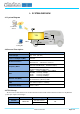
4. OPERATING CONNECTION FOR DEBUG
4.1 Evaluation Environment
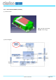
The following charts show the example of connection diagram for debugging. TCU can be powered up on the
condition as descripted in the chapter 2.2 and debugged over the UART by using the external PC. The only different
point between the external antenna model and the internal antenna model is the way to establish the RF connection.
(1)E xternalAntennaModel(J E ‑5030)
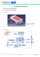
(2)InternalAntennaModel(J E ‑5031)
Test Request
Response
TCU
DC
Power
13.5V (9V~16V)
+
-
Cellular
Communication
Tester
Debug-PC
Power source
Debug
(UART)
Test Request
Response
DC
Power
13.5V (9V~16V)
+
-
Cellular
Communication
Tester
Debug-PC
Power source
Debug
(UART)
TCU
Cellular
RF Connector