
Installation manual

-6-
7. Wiring Information
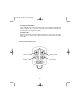
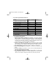
7.1 Main 12-Pin Harness
RED: +12V Battery input.
Connect to the vehicle's positive battery terminal and add a fuse within 12 inches.
GREEN: (-) Door trigger input.
Connect to the wire that shows ground when the door is open.
*
BLACK: (-) Ground input.
Connect this wire to bare metal, using a lock or star washer to prevent the screw
from coming loose. If possible, use a factory bolt, rather then a screw.
VIOLET: (+) Door trigger input.
Connect to the wire that shows +12V when the door is open.*
YELLOW: +12V ignition input.
Connect to the main ignition wire at the ignition switch. This wire must show
+
12V
when the ignition is ON and while the vehicle is cranking.
BLUE: (-) Trunk trigger input.
Connect to the wire that shows ground when the trunk/rear hatch is open.
BROWN: (+) Siren output 3A.
Connect to the siren's red wire. Connect the black wire of the siren to (-) chassis
ground. (It is recommended to ground the siren at the same point as the main unit.)
BROWN/WHITE: (-) Horn Honk / Passenger Unlock Output 500mA. (Selectable
Output)
Horn Honk Output: Connect to a relay to pulse the horn when the security system
is triggered. (See Horn Honk Relay Diagrams for assistance.)
Passenger Unlock Output: Connect to a relay to unlock the passenger doors when
the system is configured for Driver's Priority Unlocking. (See Door Lock Diagrams
for assistance.)
BLACK/WHITE: (-) Dome light supervision output 500mA.
Connect to a relay for optional dome light supervision upon disarming the security
system. (See Dome Light Supervision diagram for assistance.)
ORANGE: (-) Armed output 500mA.
This wire provides a ground output when the unit is armed. This wire can be used
to activate an optional circuit interrupt or other device (i.e.: window module, etc).
YELLOW/WHITE: (-) Auxiliary 1 output 500mA.
ms2100.qxd 4/29/2003 3:51 PM Page 6