
Installation manual

-7-
Connect to a relay for an optional feature such as a trunk release solenoid,
window module, etc.
WHITE: (+/-) Parking light output (10A relay).
The output polarity of this circuit can be selected for either (+) positive or (-)
negative output via the internal jumper. Make sure to verify the polarity of the
parking light circuit before setting the jumper.
* Diode isolate the door trigger wires for vehicles with independent door trigger
wires.
7.2 3-Pin Door Lock Harness:
Green: (
-
) Lock
Red: Not Used
Blue: (
-
) Unlock
(See Door Lock Diagrams for assistance.)
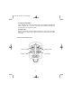
8. Starter Disable Interface
1. Using a digital multi-meter, determine the wire from the ignition harness that
shows +12V only during crank. Once the wire has been determined, cut the wire
in half and try cranking the vehicle again. The vehicle should be unable to start.
Do not cut the wire to close to the connector or ignition switch, as this will make
it difficult to make the wire connections.
2. Plug the BROWN starter disable wires (with the two female connectors) onto the
males connectors on the alarm main unit. Route the wires from the alarm main
unit to the cut starter wires in the vehicle. Be sure these wires will not interfere
with the operation of the vehicle, including movement of the steering wheel or
pedals. Connect the BROWN wires to each side of the cut starter wire.
3. To verify the connections were made properly, try starting the vehicle. The
vehicle should be able to start up. If not, double check the connection at the
alarm main unit and the vehicle's starter wires.
9. Plug-in Connectors
4-PIN WHITE CONNECTOR: Plug-in connector port for dual stage shock sensor.
3-PIN WHIE CONNECTOR: Plug-in connector port for Door Lock harness.
2-PIN BLUE CONNECTOR: Plug-in connector port for Valet/Override button.
2-PIN RED CONNECTOR: Plug-in connector port for LED indicator.
ms2100.qxd 4/29/2003 3:51 PM Page 7