installation_MS5500.
installation_MS5500.
installation_MS5500.qxd 12/6/99 11:59 AM Page 3 Table of Contents 1. 2. 3. 4. 5. 6. 7. 8. 9. 10. 11. 12. 13. 14. Before You Begin . . . . . . . . . . . . . . . . . . . . . . . . . . . . . . . . . . . . . . . . . . . . . . . . . . . . . . . . .Page 1 Installation Tips . . . . . . . . . . . . . . . . . . . . . . . . . . . . . . . . . . . . . . . . . . . . . . . . . . . . . . . . . .Page 2 Mounting Components Main Unit . . . . . . . . . . . . . . . . . . . . . . . . . . . . . . . . . . . . . . . . .
installation_MS5500.
installation_MS5500.qxd 12/6/99 11:59 AM Page 1 Before You Begin 1. Be sure to read the manual thoroughly before beginning the installation to ensure a proper understanding of the MS5500 and its functions. 2. Verify system contents: ❑ Main Unit ❑ Two 3-Button Remote Transmitters ❑ Siren ❑ Logic Sensor II ❑ Harnesses • • • • • 14-Pin main harness 4-Pin auxiliary function harness 2-Pin Status LED harness 2-Pin Override Switch harness Pre-wired starter kill relay socket with relay 3.
installation_MS5500.qxd 12/6/99 11:59 AM Page 2 Installation Tips 1. Use a Volt / Ohm meter to test all wires. Do not use a test light. 2. Good power and ground connections are essential for proper operation. 3. Route all wires from the engine compartment to the interior of the vehicle through a grommet and use electrical tape and split loom tubing for protection. 4. When adding optional accessories such as door locks, window modules, etc.
installation_MS5500.qxd 12/6/99 11:59 AM Page 3 Mounting Components Main Unit The main unit should be mounted in the interior of the vehicle. Do not mount the main unit in the engine compartment. For maximum security, avoid mounting the main unit where it will be easily accessible to a thief. If you are mounting the unit under the dash board, be sure to mount the unit as high as possible and in a location where it will not interfere with the operation of the pedals.
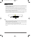
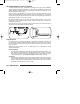
installation_MS5500.qxd 12/6/99 11:59 AM Page 4 EXT2 Extended Range Antenna (optional) The optional EXT2 is a tuned, coaxial antenna, designed to be used with the MS5500 security system to increase transmitter range. When properly installed, the EXT2 will add greater installation flexibility to the system, allowing the antenna to be placed high in the vehicle to achieve maximum range.
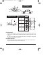
installation_MS5500.qxd 12/6/99 11:59 AM Page 5 Mounting For Shock Sensitivity Only Mounting For Shock and Motion Sensitivity Motion Sensitivity Front/Rear Side to Side Least Best Good Good Good Good Best Least Position Override Switch Mount the Override Switch in a location near the driver where it is easily accessible but not plainly visible. Plug the blue override switch connector into the blue 2-pin socket on the main unit.
installation_MS5500.
installation_MS5500.qxd 12/6/99 11:59 AM Page 7 Wiring Description 14-Pin Main Harness Pin 1 - BLACK: Ground. Connect to a solid chassis ground. Be sure to use a ring connector of proper size. Scrape away the paint at the grounding point. Pin 2 - RED: Main Power (+12v) input [3A fuse] Connect to constant +12v. A clean source of power is essential. This connection can be made at either the battery or at the constant power supply wire to the ignition switch. Be sure to install a fuse near the connection.
installation_MS5500.qxd 12/6/99 11:59 AM Page 8 Pin 11 - BLUE: Starter Defeat Normally Closed (-) output Provides a negative output while the alarm is Armed and during alarming to disable the vehicle’s starter circuits. Connect to the provided Starter Kill Relay socket as shown.
installation_MS5500.qxd 12/6/99 11:59 AM Page 9 Pin 14 - YELLOW/white: Auxiliary Function 1 negative output Provides negative (-) output. Output will stay on for as long as the Button is pressed. 4-Pin Auxiliary Function Harness Pin 1 - YELLOW/black: Auxiliary Function 2 (-) output (resets with arm and disarm). Provides a negative output to activate a relay. The output of this wire can be programmed to operate in one of three operating modes. See Programming.
installation_MS5500.qxd 12/6/99 11:59 AM Page 10 Jumper Settings Jumper Selections Parking Light Polarity. Selects the polarity (+/-) for the output of the on-board Parking Light relay. Pin 1 + Pin 2 = positive Pin 2 + Pin 3 = negative Dome Light Polarity. Entry/Exit relay. Selects the polarity (+/-) for the output of the on-board Illuminated Pin 1 + Pin 2 = positive Pin 2 + Pin 3 = negative Door Lock Pulse Width. Selects between a 1-second and a 4-second output for door locking and unlocking.
installation_MS5500.qxd 12/6/99 11:59 AM Page 11 Accessing the Jumpers Using a flathead screwdriver, carefully press in on the access tabs on the sides of the case until the hooks release. Take care not to push the tabs in too far or they may break. Once you have made your selections, close the case by aligning the top and button halves of the case, making sure that the tabs are over their mounting holes.
installation_MS5500.qxd 12/6/99 11:59 AM Page 12 Remote Transmitters Remote Transmitter Layout Button 1 LED Button 2 Mode Button Each system comes with 2 Remote Transmitters, pre-programmed to operate in the Ungo Standard Mode and will Arm and Disarm the system with chirp confirmation using Button 1. Transmitter Operating Modes The MS5500 can be configured to work with the remote transmitters in one of three ways, Ungo Standard Mode (default), Convenience Mode, or Driver Door Priority Mode.
installation_MS5500.qxd 12/6/99 11:59 AM Page 13 The Mode Button will change the function of Buttons 1 and 2 each time it is pressed, allowing Buttons 1 and 2 to control the system’s Auxiliary Function Outputs. Note also that the LED on the transmitter changes color each time the Mode Button is pressed to indicate the current function of Buttons 1 and 2. The LED will stay on for 5 seconds, then turn off, returning Buttons 1 and 2 to their off settings.
installation_MS5500.qxd 12/6/99 11:59 AM MODE none Page 14 MODE green MODE orange MODE red BUTTON 1 ARM AUX 2 not used not used BUTTON 2 DISARM*/ UNLOCK ALL not used not used not used MODE BUTTON Mode Sequence None:Green:Orange:Red:None:... *Disarming the system will unlock only the driver's door. Button 1 Arms the system. This Button also locks the doors when the system is in Valet Mode.
installation_MS5500.qxd 12/6/99 11:59 AM Page 15 Adding a New Transmitter into the System 1. Turn on the ignition. 2. Press and hold the Override switch. • The status LED will turn on red. 3. Within 5 seconds: Continue holding the Override switch and Press Transmitter Button 1* For remote arming with chirp confirmation. --- or --Release the Override switch and Press Transmitter Button 1* For remote arming without chirp confirmation.
installation_MS5500.qxd 12/6/99 11:59 AM Page 16 Programming System Initialization and Default Reset Following this procedure will set all System Programming Parameters to factory default settings. 1. Turn on ignition. 2. After 4 seconds, press and hold Buttons 1 and 2 together for 5 seconds. The siren will emit one chirp, indicating that the reset signal was received. 3. Turn ignition off. • • • • All System Programming parameters are now set to factory default settings.
installation_MS5500.
installation_MS5500.qxd 12/6/99 11:59 AM Page 18 2 chirps = Logic Sensor II 3 chirps = Optional sensor 4 chirps = hood/trunk When Audible Tamper Alert report is turned off, the siren will emit a long chirp on disarming to indicate the system was triggered, but the zone indication will be from the status LED only. 5. Door Unlock Pulse - Single/Double. Selects between a single pulse or a double pulse door unlock output.
installation_MS5500.qxd 12/6/99 11:59 AM Page 19 the 30 seconds, the output will turn off. When the Latched or Timed outputs are activated: • Arming the system will turn off the Aux. 2 output if it was turned on while the system was disarmed. • Disarming the system will turn off the Aux. 2 output if it was turned on while the system was armed. 11. Logic Sensor Defeat (Dedicated Remote Start Mode).
installation_MS5500.qxd 12/6/99 11:59 AM Page 20 Logic Sensor II Because of its advanced design, the Logic Sensor II can be set for Shock and Motion detection or Shock detection only. The way the sensor is mounted and the Motion Sensitivity jumper is set determines if motion is detected. See Mounting Components and Jumper Selections. Adjustment The shock sensitivity of the Logic Sensor II is set using the Remote Transmitter. There are 12 levels of sensitivity.
installation_MS5500.qxd 12/6/99 11:59 AM Page 21 Remote Logic Sensor II Bypass In case of extreme weather conditions such as high winds, the Logic Sensor II can be temporarily bypassed from the Remote Transmitter while the system is armed to prevent the system from false alarming. To Bypass the Logic Sensor II: 1. With the system armed, press the Mode Button on the Remote Transmitter 3 times, holding down on the third press. 2. Continue holding the Mode Button.
installation_MS5500.qxd 12/6/99 11:59 AM Page 22 Reference Chart You can use this chart to quickly identify and interpret the MS5500 system’s chirp indications and LED flashes.
installation_MS5500.
installation_MS5500.qxd 12/6/99 11:59 AM Driver Door Priority Wiring Diagrams Page 24 (-) Door Lock wire LOCK/UNLOCK SWITCH (-) Door Unlock wire White/green wire (-) LOCK White/blue wire (-) UNLOCK For a description of Driver’s Door Priority Mode, see Remote Transmitters Transmitter Operating Modes. FACTORY DOOR LOCK MODULE 15A FUSE CONNECT TO +12V Negative Trigger System For negative trigger door locking systems, wire as shown at right. CUT Yellow/white wire (-) AUX.
installation_MS5500.qxd 12/6/99 11:59 AM Page 25 Tech Tips The following are some suggested uses for the programmable Auxiliary Function 2 Output. Remote Control of Audio System (Latched Operating Mode) To Vehicle Radio Wiring Harness This enables the user to listen to the vehicle’s audio or video system for extended periods without need of the vehicle’s ignition key.
installation_MS5500.
installation_MS5500.
installation_MS5500.qxd 12/6/99 11:59 AM Page 28 MS5500 Wiring Diagram Ungo Security Corporation A Clarion Company 661 West Redondo Beach Blvd. Gardena, CA 90247 800-Go-Clarion www.clarionmultimedia © Ungo Security Corporation, Gardena, CA 98-MS5500-00 Rev.