USER GUIDE PLATINUM SERIES™ Sound Processor By Advanced Bionics
User Guide for the Platinum Series™ Sound Processor PLATINUM SERIES By Advanced Bionics
Labeling The symbols below are used on the labeling for the product and for transportation, and their meanings are as follows: CAUTION: F ederal law restricts this device to sale, distribution and use by or on the order of a physician.
Table of Contents Platinum Series Sound Processor . . . . . . . . . . . . . . . . . . . . . . . . . . . 5 Program Control . . . . . . . . . . . . . . . . . . . . . . . . . . . . . . . . . . . . . 5 Volume Control . . . . . . . . . . . . . . . . . . . . . . . . . . . . . . . . . . . . . 5 Sensitivity Control . . . . . . . . . . . . . . . . . . . . . . . . . . . . . . . . . .
Table of Figures Figure 1: Platinum Series Sound Processor . . . . . . . . . . . . . . . . . . . . . 5 Figure 2: Headpiece Color Cap Removal Tool. . . . . . . . . . . . . . . . . . . . 10 Figure 3: Removing the Headpiece Color Cap. . . . . . . . . . . . . . . . . . . . 10 Figure 4: Headpiece Clip . . . . . . . . . . . . . . . . . . . . . . . . . . . . . . . . 11 Figure 5: Headpiece with Headpiece Clip. . . .
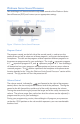
Platinum Series Sound Processor Your audiologist will demonstrate the adjustable controls of the Platinum Series Sound Processor (PSP) and instruct you on appropriate settings. Figure 1: Platinum Series Sound Processor. Program Control The program control, on the left side of the control panel, is used to turn the processor on and off, to select one of three programs, and to test the headpiece microphone.
Sensitivity Control The sensitivity control indicated by and located to the right of the volume control, determines the quietest level of sound that will be picked up from the environment by the microphone. The sensitivity control is typically set at 12:00 for daily device use. Turning the control to the left decreases the sensitivity so that softer sounds are not picked up by the microphone. This may help eliminate background noise.
Microphone/System Status When the battery and lock sequences are complete, microphone and system status can be verified. The green LED indicator will flicker in response to loud sounds presented near the microphone verifying that the microphone is receiving sound, that data is being transmitted to the implant, and that the processor is receiving information back from the implant.
Auxiliary Jack The auxiliary jack is located on the side of the processor near the control panel. The auxiliary microphone and telephone adapter provided with the system are connected here. This jack is also used to connect other external auditory input sources, such as battery-powered FM systems, MP3 players, television audio amplifiers or other assistive listening devices. The Microphone Tester Earphones provided by AB are also connected here.
Headpiece & Cable Single-Unit Headpiece The single-unit headpiece integrates the system’s microphone and transmitter in an attractive headpiece, which is easily worn directly over the implant. Two different headpieces are available for use with the processor depending on your implant type. A “flat bottom” style headpiece is used with the Clarion 1.0, 1.2 and CII Bionic Ear cochlear implants because these have a flat surface ceramic casing.
Changing the Platinum Headpiece Color Cap: Figure 2: Headpiece Color Cap Removal Tool. 1. Open the Headpiece by inserting the Headpiece Color Cap Removal Tool into the slot above the headpiece cable connector and pushing the tool straight back to lift the color cap as shown below. Figure 3: Removing the Headpiece Color Cap. 2. Close the headpiece by carefully aligning the Headpiece Color Cap on the headpiece and pressing both parts together to snap them back into place.
Headpiece Clip Figure 4: Headpiece Clip. Attaching the Headpiece Clip to the Headpiece: The Headpiece Clip is used to help keep the headpiece in place on the side of the head using some hair clipped under it to keep it from being easily bumped off. NOTE : The Headpiece Clip does not work with the curved bottom headpiece used with the HiRes 90K implant. If you have this newer model implant, please disregard the following instructions regarding use of the clip. 1.
Using the Headpiece with the Clip: 1. Hold the hair over the implant flat to the skull with the index finger of one hand. Figure 7: Placing the Headpiece. 2. Grip the headpiece and open the clip between your fingers and thumb as shown. Figure 8: Gripping the Headpiece. 3. Guide the clip along the skin and under the hair, then release when the headpiece is positioned over the implant. Figure 9: Headpiece in Place.
Cable The cable connects the headpiece to the processor and provides the pathway for relaying information between the internal and external components of the system. Cables are available in multiple lengths in either beige or brown. Each cable includes a small clip that can be used with clothing to help hold the cable in place. At one end of the cable is a two-pin plug that is inserted into the headpiece. Please note that the pins are of different diameters and must be inserted correctly.
Batteries & Battery Charger A Lithium Ion rechargeable battery or a compartment that accommodates three standard AA batteries powers your PSP. When you are not using your processor, it should be turned off; otherwise, the battery will continue to drain. NOTE: Remove the rechargeable battery or the AA battery compartment from the processor when it is not likely to be used for an extended period of time.
• Slide the battery in the direction of the lever until it disconnects from the processor. To insert the rechargeable battery or AA battery compartment: • Locate the slide tracks on the underside of the processor and the top of the battery. • Position the battery so the battery contact is toward the lever on the processor. • Guide the battery into the tracks on the processor. • Slide the battery onto the processor until it engages. • Do not force the battery into the processor.
Battery Charger The battery charger provided with your processor is designed so that two lithium ion rechargeable batteries can be charged simultaneously. It is compatible with batteries provided with the AB Platinum Series Sound Processor and the S-Series Processor only. Batteries do not need to be fully depleted before recharging. Figure 12: Battery Charger.
To charge the lithium ion rechargeable batteries: • Place charger on a flat surface. • Connect the power supply cord to the power supply. Connect the cable from the power supply to the charger. Plug power supply cord into power outlet. Figure 13: Connecting the Power Supply to the Charger. • Gently insert one or two rechargeable batteries in the charger so that the contacts on each battery match up with the contacts in the charger.
CAUTION: The charger is only designed for use with the processor lithium ion rechargeable batteries provided by AB. Do not attempt to charge off-the-shelf batteries used inside the AA battery compartment. he rechargeable batteries and charger contacts should be kept free T from dirt and dust. Dirty contacts can result in charger malfunction. Gently clean the contacts with a hearing aid brush or dry cotton swab being careful not to bend the contact pins. This should be done at least once a month.
Accessories Carrying Cases A variety of carrying cases are available for your processor. Pediatric Kits are packaged with a belt and harness case. Adult Kits come with a belt worn carrying case that is also available in additional colors and styles that can be purchased as accessories. NOTE: Nylon carrying cases are hand washable in mild soap. Air dry only; do not machine dry. Harness Case A harness with an attached case allows the processor to be worn at the child’s side.
Leather Carrying Case The belt worn leather carrying case secures the processor at the waist. A clip on the back of the case attaches it to your waistband or belt. Cable protector holes located near the belt clip extend the life of headpiece cables when used as illustrated on the following page. See Figures 18-20. Figure 17: Leather Carrying Cases. Sport Carrying Case A lined water-resistant case, which can be worn on the waist or a belt, is provided.
Extending the Life of Your Headpiece Cables 1. Plug in the cable as shown. Figure 18: Feeding the Cable. 2. Feed the cable through the far buttonhole. Figure 19: Feeding the Cable Through Far Buttonhole. 3. Feed the cable through the other buttonhole. Figure 20: Feeding the Cable Through Other Buttonhole.
Auxiliary Microphone You may find that using the auxiliary microphone (also called a lapel microphone) is preferable in some or all listening environments. The auxiliary microphone can be hand-held or worn on your lapel or collar. You may want to experiment with several microphone positions to find out which location is best for you. To use the auxiliary microphone: 1. Turn the processor off by turning the program switch to the off (o) setting. 2.
Telephone Adapter The telephone adapter provides an alternative to placing the telephone receiver next to the microphone of the headpiece or auxiliary microphone. Figure 21: Telephone Adapter. Set up the telephone adapter as follows: • Unplug the handset cord from the telephone base. • Plug the short cord into the handset jack on the telephone base. • Mount the unit in a convenient location with the adhesive pad. • Plug the handset into the modular jack on the telephone adapter.
Other Battery-Powered Audio Input Devices In addition to the accessories that are provided with the your processor, you may want to use other external audio input devices. The same auxiliary jack that is used for the auxiliary microphone or telephone adapter can be used for other batterypowered external audio input sources such as FM systems or MP3 players. Consult with your audiologist regarding which program position should be used with auxiliary audio input devices.
Using the Platinum Series Sound Processor Getting Started – Quick Steps In order to use your processor, follow the steps below: 1. Verify that the processor program switch is in the off position (o). 2. Check that a charged battery or an AA battery pack has been correctly inserted onto the processor. 3. Adjust the volume ( way to the left. ) so that the indicator notch on the control is all the 4. Check the position of the sensitivity control ( on the control is at the 12:00 position.
Adjusting for Background Noise In some situations, background noise may interfere with your ability to hear clearly. Background noise can be particularly distracting in situations where a large number of people are speaking at once or in a noisy environment. Decreasing the sensitivity of the processor by turning the sensitivity control toward the left may help eliminate some of the background noise. Using the auxiliary microphone may also be helpful.
Troubleshooting Guide The following is a description of the most common problems you may encounter with your processor and solutions for addressing those problems. After trying the remedies below, if the problem persists, contact your programming center or AB for support. No Sound Heard; No Response From User • Ensure that the cable is inserted into the processor and the headpiece is properly positioned. Turn the processor off (o) and back to position , , or .
Headpiece Falls Off • Use the cable clip to provide additional stability to prevent the headpiece from falling to the ground. • If your headpiece frequently falls off during normal activities, it may indicate the need for a stronger magnet. Contact your programming center. Headpiece or Processor Gets Wet • Turn the processor off immediately. • Remove headpiece. • Remove power source. • Contact your programming center or AB for further instructions.
Performing a System Check You can verify your system’s operating status in three simple steps: Step 1) Check battery charge status. Step 2) Check lock status. Step 3) Check microphone and system status. To assure the system’s overall proper functioning, perform all three steps. Once you get used to the steps, it takes less than one minute to complete a system check.
Step 3: Microphone and System Status When the battery and lock sequences are complete, the microphone and system status can be verified. To check the microphone and system status, turn the program control to the desired program position. Adjust the volume and sensitivity controls each to the 12:00 position. Observe the green LED indicator as you snap your fingers or speak loudly near the microphone. The green light should illuminate with each snap of your fingers and with each syllable.
engages into place on the processor. Do not force the battery. It is designed to be inserted in only one direction; forcing may jam or damage the slide mechanism. • Perform the system check sequence, Steps 1-3, as described at the beginning of this section. To Replace the AA Battery Compartment: • Unsnap the AA battery compartment utilizing the thumb recess on the top of the compartment.
Headpiece To Replace the Headpiece: • Turn the program control to the off (o) position. • Remove the headpiece from the cable by holding the cable at its strain relief portion and gently pulling the cable away from the headpiece. • Insert the two-pin plug into the replacement headpiece. Take care to match the larger pin on the plug to the larger hole of the headpiece connector. • Repeat the system check, steps 1-3. NOTE: Be sure the processor is turned off before removing the headpiece cable.
Table 1: Troubleshooting Action Table Troubleshooting Action Table PROBLEM ACTION During battery status check, no flash or only one flash is observed. • Replace rechargeable battery or AA battery pack. • If there are no blinks after replacement, clean the contacts with a hearing aid brush or dry cotton swab. • If problem continues, contact your cochlear implant center. Red LED indicator continuously blinks at one-second intervals – and/or – audible alarm, if activated, sounds at one-second intervals.
Caring for Your Cochlear Implant System Although your processor has been designed and built to withstand daily wear and tear, care must be taken to protect both the implanted and external components of the system. For a detailed discussion of clinical results, warnings and precautions please refer to the package insert supplied separately. It is a good idea to carry your Patient Identification Card with you at all times.
To maintain and improve the life of the headpiece microphone we recommend that you store your headpiece in a Dry Aid kit overnight or when not in use. A Dry Aid kit is available separately for purchase from AB and other sources. While the processor has been built to be as sturdy as possible, it should be treated with gentle care and attention. Additionally, you should check your cable regularly (every week or so) to see if it is frayed or damaged. Avoid making sharp bends or kinks with the cable.
You should take the following basic precautions in order to reduce the chances of an ESD event: • Electrostatic potential can be safely reduced by touching any person or object with your fingers prior to contact with a headpiece, cables or sound processor. Hand contact will safely equalize electric charge and prevent sparks from jumping to the processor system. When approached by someone (for example on carpet), touch him or her first with your hand prior to them touching your external components.
Contact Us Advanced Bionics is committed to providing the highest quality products and service to our customers. We welcome your comments regarding the Platinum Series Sound Processor or your suggestions to improve our products. Please feel free to contact Advanced Bionics or discuss your suggestions with your implant professional. NORTH AMERICA Advanced Bionics, LLC 12740 San Fernando Road Sylmar, CA 91342 USA 877.829.0026 in US and Canada 800.678.3575 TTY 661.362.1400 661.362.
Advanced Bionics, Platinum Series™, and IntelliLink™ are trademarks of Advanced Bionics, LLC in the United States of America and other countries. This device is protected under one or more of the following U.S.
www. AdvancedBionics.com NORTH AMERICA Advanced Bionics, LLC 12740 San Fernando Road Sylmar, CA 91342 USA 877.829.0026 in US and Canada 800.678.3575 TTY 661.362.1400 661.362.1500 Fax info@AdvancedBionics.com Asia-Pacific Advanced Bionics Asia-Pacific Limited Suite 4203, 42/F, Tower One Lippo Centre, 89 Queensway Hong Kong 852.2526.7668 852.2526.7628 Fax AP@AdvancedBionics.com Europe Advanced Bionics SARL 76 rue de Battenheim 68170 Rixheim, France +33.3.89.65.98.00 +33.3.89.65.50.