Model S100 installation guide NOTE: This product is intended for installation by a professional installer only! Any attempt to install this product by any person other than a trained professional may result in severe damage to a vehicle’s electrical system and components.
table of contents primary harness (H1) wire connection guide . . . . . . . . . . . . . . . . . . . . . . . . . . . . . . . . . . . . . . .4 primary harness wiring diagram . . . . . . . . . . . . . . . . . . . . . . . . . . . . . . . . . . . . . . . . . . . . . . . .4 primary harness wiring instructions . . . . . . . . . . . . . . . . . . . . . . . . . . . . . . . . . . . . . . . . . . . . .4 door lock harness (H2), 3-pin connector . . . . . . . . . . . . . . . . . . . . . . . . . . . . . . . . . . . . . . .
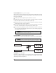
primary harness (H1) wire connection guide primary harness wiring diagram H1/1 ___ ORANGE H1/2 ___ WHITE H1/3 ___ WHITE/BLUE H1/4 ___ BLACK/WHITE H1/5 ___ GREEN H1/6 ___ BLUE H1/7 ___ VIOLET (+) Door Trigger Input, Zone 3 H1/8 ___ BLACK (-) Chassis Ground Input H1/9 ___ YELLOW H1/10 ___ BROWN H1/11 ___ RED H1/12 ___ RED/WHITE (-) 500 mA Armed Output (+)/(-) Selectable Light Flash Output (-) 200 mA Channel 3 Programmable Output (-) 200 mA Domelight Supervision Output (-) Door Trigge
H1/2 WHITE (+/-) light flash output As shipped, the H1/2 WHITE wire should be connected to the (+) parking light wire. If the light flash polarity jumper is moved to the (-) position (see the Programming Jumper section of this installation guide), this wire supplies a (-) 200 mA output. This is suitable for driving (-) light control wires in Toyota, Lexus, BMW, some Mitsubishi, some Mazda, and other models.
H1/3 WHITE/BLUE 200 mA (-) channel 3 output This wire provides a (-) 200 mA output whenever the remote button(s) controlling Channel 3 is pressed. This output can be programmed to provide the following types of output (see System Features Learn Routine section of this guide): ➤ A validity output will send a signal as long as the transmission is received. ➤ A latched output will send a signal continuously when the Channel 3 button(s) is pressed and released.
NOTE: If using a door trigger wire that has a delay, Advanced Menu 2, feature 6, or the Pro Security Programmer can be used to turn the notification of a bypassed (open) zone off. H1/6 BLUE (-) instant trigger input This input will respond to a negative input with an instant trigger. It is ideal for hood and trunk pins and will report on Zone 1. It can also be used with single-stage sensors.
H1/9 YELLOW (+) ignition input Connect this wire to the (+) 12 volts ignition wire. This wire is pre-wired to the starter kill relay and must show (+) 12 volts with the key in RUN position and during cranking. Take great care that this wire cannot be shorted to the chassis at any point. \\\\\\\ H1/10 BROWN (+) siren output Connect this to the RED wire of the siren. Connect the BLACK wire of the siren to (-) chassis ground, preferably at the same point you connect the control module’s BLACK ground wire.
H1/12 RED/WHITE 200 mA (-) channel 2 output When the system receives the code controlling channel 2 for longer than 1.5 seconds, the RED/WHITE will supply an output as long as the transmission continues. This is often used to operate a trunk/hatch release or other relay/driven function. IMPORTANT! Never use this wire to drive anything but a relay or a low-current input! The transistorized output can only supply 200 mA of current.
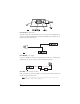
peripheral plug-in harnesses LED, 2-pin WHITE plug The LED operates at (+) 2 volt DC and plugs into the two-pin WHITE port. Make sure the LED wires are not shorted to ground as the LED will be damaged. Multiple LED’s can be used, but they must be wired in series. The LED fits into a 9/32-inch mounting hole. Be sure to check for clearance prior to drilling the mounting hole. NOTE: Never use a BLUE LED in combination with a RED LED.
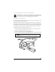
pro security programmer Interface, 3-Pin BLACK plug The BLACK three-pin port is provided for programming of the unit. When using the Pro Security Programmer, it is possible to configure any and all of the programmable functions. For more information please refer to the guide packaged with the programmer. mounting the receiver/antenna Receiver/antenna position should be discussed with the vehicle’s owner prior to installation, since the antenna may be visible to the vehicle’s operator.
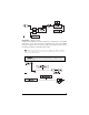
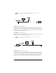
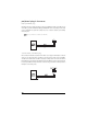
shock sensor harness, 4-pin WHITE plug GREEN (-) Multiplex Input Inputs shorter than 0.8 seconds will trigger the warning response, while inputs longer than 0.8 seconds will trigger full alarm sequence and report Zone 4. NOTE: If installing an optional dual-stage sensor, connect to the GREEN wire. The following diagram eliminates the need for diodes to isolate the sensors, as well as providing a separate zone for each sensor. Diagram for adding optional dual stage sensor to GREEN wire (zone 4).
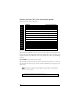
light flash jumper This jumper is used to determine the light flash output. In the (+) position, the on-board relay is enabled and the unit will output (+)12V on the WHITE wire, H1/2. In the (-) position, the on-board relay is disabled. The WHITE wire, H1/2, will supply a 200 mA (-) output suitable for driving factory parking light relays. NOTE: For parking light circuits that draw 10 amps or more, the jumper must be switched to a (-) light flash output.
1. Open a door. (The H1/5 GREEN wire or the H1/7 VIOLET wire must be con- nected.) 2. Ignition. Turn the ignition on, then back off: (The H1/9 YELLOW wire must be connected.) 3. Select a Menu. Press and HOLD the Override switch: (The Override switch must be plugged into the blue port.) After three seconds the siren will chirp once indicating entry to the Basic Features Menu #1. If this is the menu you wish to access, release the button and go on to Step 4.
2. Then press the Override switch once more and hold it. For example, if you just programmed the third feature in the menu and you would like to program the seventh feature in the menu, you would press and release the Override switch four times and then press it once more and hold it. The siren would chirp seven times to confirm access to the seventh feature. To select another menu: 1. Press and hold the Override switch. 2.
menu #2 - advanced features Feature Number One Chirp Setting Two-Chirp Setting 2-1 Siren Horn honk 2-2 30-second siren duration 60-second siren duration 2-3 False alarm prevention Circuitry ON False alarm prevention Circuitry OFF 2-4 Progressive door trigger Instant door trigger 2-5 Override switch input: 1 pulse Override switch input: 2-5 pulses 2-6 Open Zone Bypass Notice ON Open Zone Bypass Notice OFF 2-7 Ignition-controlled domelight ON Ignition-controlled domelight OFF 2-8 Sing
1-4 ACTIVE/PASSIVE LOCKING: If passive arming is selected in step 1-1, then the system can be programmed to either lock the doors when passive arming occurs, or only lock the doors when the system is armed via the remote. Active locking means the system will not lock the doors when it passively arms. Passive locking means that the system will lock the doors when it passively arms. NOTE: Remember, when passive arming is selected, the unit will chirp 20 seconds after the last door is closed.
menu #2 - advanced features 2-1 SIREN/HORN HONK: The system can be programmed to output pulses instead of a continuous output when the system is triggered. This is useful to honk the factory horn in applications where a siren is undesirable. Remember that the unit is only capable of supplying 1 amp of current. A relay will be required to interface with most factory horn systems. 2-2 SIREN DURATION 30/60 SECONDS: It is possible to program the unit to sound for 30 or 60 seconds during the triggered sequence.
ative pulses instead of a single pulse. At the same time, the GREEN H2/A wire will supply two positive pulses instead of a single pulse. This makes it possible to directly interface with double pulse vehicles without any extra parts. 2-9 CHANNEL 3 VALIDITY/LATCHED/LATCHED RESET WITH IGNITION/30 SECOND TIMED/SECOND UNLOCK OUTPUT: Channel 3 can be programmed for these output configurations. The unit is set to the default validity output.
Channel Number Function Wire Color 1 Arm/Disarm/Panic 2 Silent Arm-Disarm/Remote Override/Trunk Release RED/WHITE 3 Remote engine start or other accessories WHITE/BLUE 4 Arm only 5 Disarm only 6 Panic only 7 Auto-learn Standard Configuration* 8 Auto-learn Single Button Arm/Disarm Configuration* 9 Delete all remotes *NOTE: For Auto Learn Configurations, see Remote Configurations section of this guide. 4.
remote configurations The remotes can be programmed with the standard or single button arm/disarm configurations by using the Auto Learn functions in the Remote Programming Routine. standard configuration A remote that uses the standard configuration operates similarly to many factory keyless entry remotes. A standard configuration remote allows arming, disarming, and Panic Mode activation with separate buttons.
diagnostics The system’s microprocessor monitors and reports all active and violated zones when arming and disarming. LED flashes indicate the active or violated zone; siren chirps indicate system status. arm/disarm diagnostics The number of siren chirps will indicate the status of the system when arming and disarming. For information on which zone is active or has been violated refer to the Table of Zones.
security diagnostics The system stores the last two full triggers in memory. These are not erasable. Each time the unit sees a full trigger, the older of the two triggers in memory will be replaced by the new trigger. To access long term event history: 1. With the ignition off, press and hold the Override switch. 2. Turn on the ignition. 3. Release the Override switch. 4. Press and release the Override switch within five seconds.
power-up power-up ensures that the when the system is powered up it will return to the same state it was in when power is disconnected. For a full description of power-up refer to the Owner's Guide. troubleshooting Starter kill doesn’t work. ➤ Is the correct starter wire being interrupted? If the car starts when the starter kill relay is completely disconnected, the wrong starter wire has been cut and interrupted. ➤ YELLOW wire is not connected to true ignition. It is connected to an accessory circuit.
Door input does not respond with the progressive trigger, but with immediate full alarm. ➤ What zone does the LED indicate? If the LED indicates that the impact sensor caused the trigger, the sensor may be detecting the door opening. Reducing the sensitivity or relocating the sensor can often solve this problem. If the LED indicates that the door caused the trigger, you may have programmed the progressive door trigger off. (See Feature 2-4 in the Feature Descriptions section of this guide.
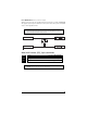
wiring quick reference guide 26
Get Started Get Protected Ungo Pro Security 661 W. Redondo Beach Blvd. Gardena, Ca. 90247 800-GO-CLARION © 2003 Directed Electronics, Inc.