Model S400 installation guide NOTE: This product is intended for installation by a professional installer only! Any attempt to install this product by any person other than a trained professional may result in severe damage to a vehicle’s electrical system and components.
table of contents primary harness (H1) wire connection guide . . . . . . . . . . . . . . . . . . . . . . . . . . . . . . . . . . . . . . .4 primary harness wiring diagram . . . . . . . . . . . . . . . . . . . . . . . . . . . . . . . . . . . . . . . . . . . . . . . .4 relay harness wire connection guide . . . . . . . . . . . . . . . . . . . . . . . . . . . . . . . . . . . . . . . . . . . . .9 relay harness wiring diagram . . . . . . . . . . . . . . . . . . . . . . . . . . . . . . . . . . . . . . . . . . . .
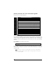
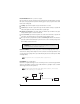
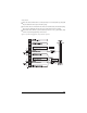
primary harness (H1) wire connection guide primary harness wiring diagram H1/1 ___ ORANGE H1/2 ___ WHITE H1/3 ___ WHITE/BLUE H1/4 ___ BLACK/WHITE H1/5 ___ GREEN H1/6 ___ BLUE H1/7 ___ VIOLET (+) Door Trigger Input, Zone 3 H1/8 ___ BLACK (-) Chassis Ground Input H1/9 ___ YELLOW H1/10 ___ BROWN H1/11 ___ RED H1/12 ___ RED/WHITE (-) 500 mA Armed Output (+)/(-) Selectable Light Flash Output (-) 200 mA Channel 3 Programmable Output Domelight Supervision Relay Output #30 (-) Door Trigger
H1/2 WHITE (+/-) light flash output As shipped, the H1/2 WHITE wire should be connected to the (+) parking light wire. If the light flash polarity jumper is moved to the (-) position (see the Programming Jumper section of this installation guide), this wire supplies a (-) 200 mA output. This is suitable for driving (-) light control wires in Toyota, Lexus, BMW, some Mitsubishi, some Mazda, and other models.
H1/3 WHITE/BLUE 200 mA (-) channel 3 output This wire provides a (-) 200 mA output whenever the remote button(s) controlling Channel 3 is pressed. This output can be programmed to provide the following types of output (see System Features Learn Routine section of this guide): ➤ A validity output will send a signal as long as the transmission is received. ➤ A latched output will send a signal continuously when the Channel 3 button(s) is pressed and released.
H1/6 BLUE (-) instant trigger input This input will respond to a negative input with an instant trigger. It is ideal for hood and trunk pins and will report on Zone 1. It can also be used with single-stage sensors. The H1/6 blue instant trigger wire can also be used to shunt sensors during operation of auxiliary channels or remote start. (See Bypassing Sensor Inputs section of this guide.) H1/7 VIOLET (+) door trigger input This type of dome circuit is used in many Ford products.
H1/9 YELLOW (+) ignition input Connect this wire to the (+) 12 volts ignition wire. This wire is pre-wired to the starter kill relay and must show (+) 12 volts with the key in RUN position and during cranking. Take great care that this wire cannot be shorted to the chassis at any point. \\\\\\\ H1/10 BROWN (+) siren output Connect this to the RED wire of the siren. Connect the BLACK wire of the siren to (-) chassis ground, preferably at the same point you connect the control module’s BLACK ground wire.
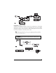
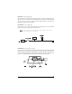
relay harness wire connection guide relay harness wiring diagram H2/A ___ RED/WHITE H2/B ___ BLACK/WHITE DomeLight Supervision relay Input #87 H2/C ___ WHITE/BLACK Lock #87a Normally Closed H2/D ___ GREEN/BLACK Lock #30 Common (Output) H2/E ___ VIOLET/BLACK* Lock #87 Normally Open (Input) H2/F ___ BROWN/BLACK Unlock #87a Normally Closed H2/G ___ BLUE/BLACK Unlock #30 Common (Output) H2/H ___ VIOLET* Channel 2 Relay Input #87 Unlock #87 Normally Open (Input) *NOTE: VIOLET and VIOLET/B
door lock harness wire connection guide identifying the door lock system The easiest way to determine which type of door lock system you are working with is to remove the master locking switch itself, which is usually on the driver’s door or on the center console. Once you have determined which type of factory door lock circuit you are working with, and the color codes of the switch wires to be used, you can usually simplify the installation by locating the same wires in the vehicle’s kick panel.
At the Switch ➤ Three-wire switches will have either a constant ground input or a constant (+)12V input, along with the pulsed lock and unlock outputs to the factory relays. ➤ Some vehicles have no external switch. The switches are inside the actuator, and instead of pulsing, the proper wires will flip-flop from (+)12V to (-) ground as the door locks are operated.
type B: negative-triggered, relay-driven system type C: reversing polarity system Use these instructions if the power door lock switch has four or five heavy-gauge wires. This type of switch has two outputs that rest at (-) ground. IMPORTANT! To interface with these systems, you must cut two switch leads. The relays must duplicate the factory door lock switches’ operation.
IMPORTANT! If these wires are not connected properly, you will send (+)12V directly to (-) ground, possibly damaging the alarm or the factory switch. ➤ H2/C WHITE/BLACK - Once both door lock wires are located and cut, connect the white/black wire to the master switch side of the lock wire. The master switch side will show (+)12V when the master switch is operated to the lock position and (-) ground when the master switch is in the middle position.
14
type D: adding one or more after-market actuators Vehicles without factory power door locks require the installation of one actuator per door. This requires mounting the door lock actuator inside the door. Other vehicles may only require one actuator installed in the driver's door if all door locks are operated when the driver's lock is used.
type E: electrically-activated vacuum This system is found in Mercedes-Benz and Audi 1985 and newer. The door locks are controlled by an electrically activated vacuum pump. Control wire will show +12V when doors are unlocked and (-) ground when doors are locked. IMPORTANT! The system must be programmed for 3.5 second door lock pulses.
type F: one-wire system This system usually requires a negative pulse to unlock, and cutting the wire to lock the door. (With some vehicles, these are reversed.) It is found in the late-model Nissan Sentra, some Nissan 240SX, and Nissan 300ZX 1992-up. It is also found in some Mazda MPV's. IMPORTANT! Remember that the violet jumper between the #87 lock terminal and the #87 unlock terminal must be cut.
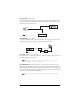
type G: positive (+) multiplex The door lock switch or door key cylinder may contain either one or two resistors. Single-Resistor Type If one resistor is used in the door lock switch/key cylinder, the wire will pulse (+)12V in one direction and less than (+)12V when operated in the opposite direction. Two-Resistor Type If two resistors are used in the factory door lock switch/key cylinder, the switch/key cylinder will read less than (+)12V in both directions.
type G door lock system wiring diagram: 19
type H: negative (-) multiplex The system is most commonly found in 1999 and newer Grand Am and Alero models, in 2000 and newer Impala and Monte Carlo models, and in Chrysler and Mazda models. The door lock switch or door key cylinder may contain either one or two resistors. Single-Resistor Type If one resistor is used in the door lock switch/key cylinder, the wire will pulse ground in one direction and resistance to ground when operated in the opposite direction.
type H door lock system wiring diagram: peripheral plug-in harnesses LED, 2-pin WHITE plug The LED operates at (+) 2 volt DC and plugs into the two-pin WHITE port. Make sure the LED wires are not shorted to ground as the LED will be damaged. Multiple LED’s can be used, but they must be wired in series. The LED fits into a 9/32-inch mounting hole. Be sure to check for clearance prior to drilling the mounting hole. NOTE: Never use a BLUE LED in combination with a RED LED.
override switch, 2-pin BLUE plug The Override switch should be accessible from the driver’s seat. It plugs into the BLUE port on the side of the unit. Since the system features Override by using the remote, the button can be well hidden. Consider how the button will be used before choosing a mounting location. Check for rear clearance before drilling a 9/32-inch hole and mounting the button.
Important! To achieve the best possible range, DO NOT leave the antenna cable bundled under the dash. Always extend the cable full length during installation, regardless of the antenna mounting location. shock sensor harness, 4-pin WHITE plug GREEN (-) Multiplex Input Inputs shorter than 0.8 seconds will trigger the Warning response, while inputs longer than 0.8 seconds will trigger full alarm sequence and report Zone 4. NOTE: If installing an optional dual-stage sensor, connect to the GREEN wire.
programming jumper light flash jumper This jumper is used to determine the light flash output. In the (+) position, the on-board relay is enabled and the unit will output (+)12V on the WHITE wire, H1/2. In the (-) position, the on-board relay is disabled. The WHITE wire, H1/2, will supply a 200 mA (-) output suitable for driving factory parking light relays. NOTE: For parking light circuits that draw 10 amps or more, the jumper must be switched to a (-) light flash output.
BLUE WIRE H1/6 ZONE 1 INPUT TO OPTIONAL HOOD/ TRUNK PINS OR SENSORS CONTROL UNIT 1N4004 DIODES REMOTE START UNIT BLUE (-) STATUS OUTPUT module programming The System Features Learn Routine dictates how the unit operates. Due to the number of steps, they have been broken up into two menus. It is possible to access and change any of the feature settings using the Override switch. However, this process can be greatly simplified by using the Pro Security Programmer.
NOTE: The Override pulse count feature (2-5) and the Channel three timed output (2-9) have five possible settings each. Pressing 6. will toggle through all the two-chirp settings. Release the Override Switch. Once a feature is programmed: ➤ Other features can be programmed within the same menu. ➤ Another menu can be selected. ➤ The learn routine can be exited if programming is complete. To access another feature in the same menu: 1.
module programming menus menu #1 - basic features Items in bold text have been programmed to the default setting at the factory. Feature Number One Chirp Setting Two-Chirp Setting 1-1 Active arming Passive arming 1-2 Chirps ON Chirps OFF 1-3 Ignition controlled door locks ON Ignition controlled door locks OFF 1-4 Active locking only Passive locking 1-5 Panic with ignition ON No panic with ignition on 1-6 0.8 second door lock pulses 3.
feature descriptions The features of the system are described below. Features that have additional settings that can be selected only when programming with the Pro Security Programmer are indicated by the following icon: menu #1 - basic features 1-1 ACTIVE/PASSIVE ARMING: When active arming is selected, the system will only arm when the remote is used. When set to passive, the system will arm automatically 30 seconds after the last door is closed.
its normal rate when the ignition is turned off to indicate that Automatic Engine Disable is active and will interrupt the starter in 30 seconds. Automatic Engine Disable does not occur in valet mode and can be bypassed using the emergency override procedure. The remote can also be used to disarm Automatic Engine Disable. 1-9 ARMED WHILE DRIVING/ANTI-CARJACKING SYSTEM: In the default setting (Armed While Driving), the system can be armed with the ignition on.
2-5 OVERRIDE PULSE COUNT ONE TO FIVE PULSES: The system can be programmed to count the number presses of the valet button before disarming the security or Anti-Carjacking system. The factory default setting is one pulse. The unit can be set for two to five pulses using the two-chirp setting to select the pulse count. Hidden Switch Option: For added security, the GRAY wire on the two-pin Override switch can be connected to any switch in the vehicle that provides a positive (+) momentary pulse.
3. Select the receiver channel: Press and release the Override switch the number of times necessary to access the desired channel. NOTE: If adding a remote, a button must be taught to the unit in the Channel 1 or Channel 4 position prior to programming other channels. Press and hold the Override switch once more. The siren will chirp and the LED will blink the number of times corresponding to the channel that is accessed.
To exit the learn routine: One long chirp indicates that Learn Routine has been exited. Learn Routine will be exited if any of the following occurs: ➤ ➤ ➤ ➤ Ignition is turned off. Door is closed. Override switch is pressed too many times. More than 15 seconds elapse between steps. remote configurations The remotes can be programmed with the standard or single button arm/disarm configurations by using the Auto Learn functions in the Remote Coding section.
diagnostics The system’s microprocessor monitors and reports all active and violated zones when arming and disarming. LED flashes indicate the active or violated zone; siren chirps indicate system status. arm/disarm diagnostics The number of siren chirps will indicate the status of the system when arming and disarming. For information on which zone is active or has been violated refer to the Table of Zones.
security diagnostics The system stores the last two full triggers in memory. These are not erasable. Each time the unit sees a full trigger, the older of the two triggers in memory will be replaced by the new trigger. To access long term event history: 1. With the ignition off, press and hold the Override switch. 2. Turn on the ignition. 3. Release the Override switch. 4. Press and release the Override switch within five seconds.
false alarm prevention circuitry False alarm prevention circuitry bypasses any zone that triggers the system more than three times within a one-hour period. For a full description refer to the Owner's Guide. Important: When testing the systems sensor and trigger inputs reset the false alarm prevention circuitry by turning on the ignition after every third system trigger. power-up power-up ensures that the when the system is powered up it will return to the same state it was in when power is disconnected.
the sensor may be detecting the door opening. Reducing the sensitivity or relocating the sensor can often solve this problem. If the LED indicates that the door caused the trigger, you may have programmed the progressive door trigger off. (See Feature 2-4 in the Feature Descriptions section of this guide.) The Override switch doesn’t work. ➤ Is it plugged into the correct socket? Check the module programming for the programmed Override pulse count. Status LED doesn’t work.
wiring quick reference guide 37
38
Get Started Get Protected Ungo Pro Security 661 W. Redondo Beach Blvd. Gardena, Ca. 90247 800-GO-CLARION © 2003 Directed Electronics, Inc.