
User Guide


12
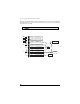
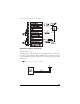
type B: negative-triggered, relay-driven system
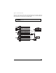
type C: reversing polarity system
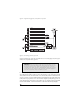
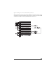
Use these instructions if the power door lock switch has four or five heavy-gauge wires. This type of
switch has two outputs that rest at (-) ground.
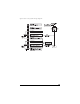
It is critical to identify the proper wires and locate the master switch to interface properly. Locate wires that
show voltage when the switch is moved to the lock or unlock position. Cut one of the suspect wires and
check operation of the locks from both switches. If one switch loses all operation in both directions then
you have cut one of the correct wires and the switch that is entirely dead is the master switch. If both switch-
es still operate in any way and one or more door motors have stopped responding entirely, you have cut
a motor lead. Reconnect it and continue to test for another wire. Once both wires have been located and
the master switch identified, cut both wires and interface as described in the following paragraphs.
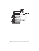
IIMMPPOORRTTAANNTT!!
To interface with these systems, you must cut two switch leads. The relays must
duplicate the factory door lock switches’ operation. The master switch will have one or two
ground inputs, one (+)12V input, and two switch outputs going directly to the slave switch
and through to the motors. These outputs rest at (-) ground. The lock or unlock wire is
switched to (+)12V, while the other wire is still grounded, thus completing the circuit and
powering the motor. This will disconnect the switch from the motor before supplying the
motor with (+)12V, avoiding sending (+)12V directly to (-) ground.