
User Guide


13
➤➤
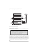
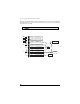
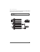
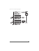
H2/C WHITE/BLACK - Once both door lock wires are located and cut, connect the white/black
wire to the master switch side of the lock wire. The master switch side will show (+)12V when the
master switch is operated to the lock position and (-) ground when the master switch is in the middle
position.
➤➤
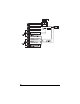
H2/D GREEN/BLACK - Connect the green/black wire to the other side of the lock wire. This is the
motor side of the lock wire and it goes to the lock motor through the slave switch.
➤➤
H2/E VIOLET/BLACK - This wire must be connected to a constant (+)12 volts. The best connection
point for this wire is the constant (+)12V supply for the door lock switch, or directly to the positive
(+) battery post with a fuse at the battery post.
NNOOTTEE::
Except in GM cars with Retained Accessory Power (RAP). In these vehicles, the (+)12V feed to the
door lock switches is turned off if the doors are closed for any length of time.
NNOOTTEE::
Most direct-wired power lock systems require 20-30 amps of current to operate. Connecting the
violet/black wire to a poor source of voltage will keep the door locks from operating properly.
➤➤
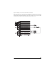
H2/F BROWN/BLACK - Connect the brown/black wire to the master switch side of the unlock wire.
The master switch side will show (+)12V when the master switch is in the unlock position and (-)
ground when the master switch is in the middle position.
➤➤
H2/G BLUE/BLACK - Connect the blue/black wire to the other side of the unlock wire.
IIMMPPOORRTTAANNTT!!
If these wires are not connected properly, you will send (+)12V directly to (-)
ground, possibly damaging the alarm or the factory switch.