
User Guide

9
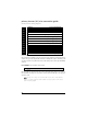
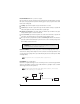
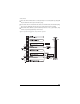
relay harness wire connection guide
relay harness wiring diagram
___
___
___
___
___
___
___
___
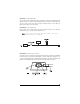
**NNOOTTEE::
VIOLET and VIOLET/BLACK are common at fuse holder.
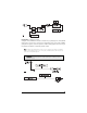
relay harness wiring instructions
H2/A RED/WHITE input to on-board channel 2 (trunk release) relay
This wire is used to supply voltage to the output H1/12. If you want a positive output on H1/12, con-
nect this wire to (+) 12 volts. Always fuse appropriately. If a negative output is desired, connect this
wire to chassis ground.
H2/B BLACK/WHITE input to domelight supervision relay
This wire is used to supply voltage to the output H1/4. If you want a positive output on H1/4, connect
this wire to (+) 12 volts. Always fuse appropriately. If a negative output is desired, connect this wire to
chassis ground.
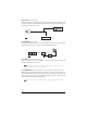
H2/C - H2/8 power door locks
The system has door lock relays on-board, and can directly interface with most electric power door lock
systems drawing 30 amps or less. It can also drive aftermarket actuators directly.
VIOLET* Unlock #87 Normally Open (Input)
BLUE/BLACK Unlock #30 Common (Output)
BROWN/BLACK Unlock #87a Normally Closed
VIOLET/BLACK* Lock #87 Normally Open (Input)
GREEN/BLACK Lock #30 Common (Output)
WHITE/BLACK Lock #87a Normally Closed
BLACK/WHITE DomeLight Supervision relay Input #87
RED/WHITE Channel 2 Relay Input #87
H2/A
H2/B
H2/C
H2/D
H2/E
H2/F
H2/G
H2/H