SIRIUS SATELUTE RADIO RECEIVER CONTROLLER CONTROLADOR DEL SINTONIZADOR SIRIUS DE RECEPCION RADIO VIA SATEUTE \/ ~\ SIRIUS Satellite Radio
Thank you you for for purchasing purchasing this this Clarion DSC920S. Thank Please read read this this owner’s owner's manual manual in in its its entirety entirety before before operating operating this this equipment. equipment. ** Please After reading reading this this manual, manual, be be sure sure to to keep keep itit in in aa handy handy place place (e.g., (e.g., glove glove compartment). compartment).
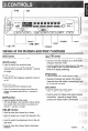
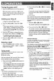
Names of the Buttons and their Func [SAT] e buttonn Used to turn turn the the power power on or or off. •* Used [BAND] button • Used to switch the reception band. 0 Used Used to switch switch the the Tuning Tuning mode mode (seek! (seek/ manual) when pressed and and held held for for 1 second second manual) when pressed longer. or longer. @ [CAT] button i he Category Category selection selection mode mode on •@Used to turn the or off. [SCAN] outton o oe Used to perform the category scan.
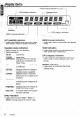
Preset _.•.• Preset channel channel indication indication (1 (1 to 6) x.-.- --- ----.
Turning the power on/off 3. Press or[I»]for 1$ Press and and hold hold the the [<
Operations ~ Manual casual memory memory 1. Select to be be memorized. memorized. Select a channel channel to Receiving statkms selected by category 2. Press the [P-M] button to enter the Preset memory mode. 1. Press the [CAT]] button button to to enter enter the the category category selection mode.
Switching the screen saver i. Press the [88] button to to switch switch the the screen screen $1 button saver. Each Each time time the the button button is pressed, pressed, the the saver. screen saver saver is is switched switched in the the order order of of OFF screen ... SS1 ... S82 ... OFF. '" If the the screen screen saver saver is turned turned on and the button button :I: operation is performed, performed, the the screen screen saver saver operation mode mode is released. released.
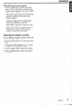
Before Installation This set set is is exclusively exclusively for for use use in in cars cars with with aa 1. This negative ground, ground, 12 12 VV power power supply. supply. negative 2. Read Read these these instructions instructions carefully. carefully. 2. Be sure sure to to disconnect disconnect the the battery battery IL” "-" terminal terminal 3. Be before starting. starting. This This is is to to prevent prevent short short circirbefore cuits during during installation. installation.
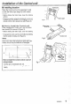
Installation of the Control unit II Installing location Dashboard --,'rr~/t. '( Place the Control unit on the passenger's seat seat e passenger’s or to the the center center or stick stick the the Velcro Velcro tape tape (large (large A) to console. console. "'(: Before sticking tape, clean clean the sticking sticking sticking the Velcro tape. surface. surface.
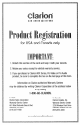
Product Registration for USA and Canada only IMPORTAN1\ etachthis this section sectionof the the card cardand keepit with i. Detach and keep with your your records. records. retain your yoursales salesreceipt receiptto to validate validatewarranty warrantyservice. service. 2., Retain 3, IfIf you youpurchased purchasesa Clarion ClarionADX ADXSeries, Series,Pro ProVideo or Pro ProAudio 3.
II PLEASEPLACE I FIRST-CLiISS HERE (Post OffiCf: will not denver without proper postage,) CLARION SALES CORPORATION PO BOX 863 BREA CA 92822-0863 ! '
1, I~ i i! i i; 1 iIi i ii i i; i i!i i I3 I I1 u ia HilS PAGE AND KEEP IT WITH YOUR REGEl This productis warranted warrantedagainst againstall all defects defectsin in material materialworkmanship ~~~k~at~shi~for a period periodof one yearfrom the date date of original original purchase. purchase.
User Guide and Product Data Sheet The Clarion FM200 is a two-channel stereo FM modulator with selectable FM frequencies, variable gain, and a remote on/off on/off switch. It~I!.?Wstheaddjtion It allows the addition of auxiliary audio sources to any FM FM radio (even those lacking auxiliary inputs). It can be used more. VD players, videocassette with DVD videocassette players, MP3 players, and more.
Installation Instructions Frequency -Selector Switch Level Matching Control ~'~'~:7'e;,.",~_•.•..•• -.I'6!'il:~) f"/::.:...---------..-"'w.,,-~--__r.:;./· 1. Find a suitable location location for the the On I/ Off Off switch switc Installation Be sure that it issVllithin within easy easy reach reach of of the the driver driver and from the and can can be operated operated safely safely from the seated seated position. position. [][] 88.
Owner's manual Mode #1'""->"<>f,,,,,; Manual de Instrucclcmes SIRIUS SATELLITE RADIO RECEIVER SINTONIZADOR SIRIUS DE RECEPCION RADIO SATELITE 9!2, \ SIRIUS Satellite Radio
Clarion product. product. you for forpurchasing purchasing this this ~~ar~~~ Thank you read this this owner’s owner's manual manual inin its its entirety entirety before before operating operating this this equipment. equipment. :I:Please read * After reading reading this this manual, manual, be be sure sure to to keep keep itit inin aa handy handy place place (e.g., (e.g., glove glove compartment). compartment).
f 1. The when starting The first first time time or when starting after after turning turning off off the lhe backup backup power power supply, supply, the the receiver receiver does does not not operate operate normally normally until until reception. reception. The The sound sound is not heard heard until until 20 or 30 secseconds onds after after reception. reception. 2.
What is Sirius Satellite Radio? \/ ~, SIRIUS Satellite Radio Sirius is is radio radio the the way way itit was was meant meant to to be: be: Up Up to to Sirius of digital digital quality quality programming programming 100 new new channels channels of 100 delivered to to listeners listeners coast coast to to coast coast via via satellite. satellite. delivered That means means 50 50 channels channels of of completely completely commercommerThat cial-free music. music.
Source unit buttcms, example 1 [ROTARY] [SC] [RD] Source unit butto.ns, example 2 Notes: The above above illustrations ilk&rations show show two two source source units units as as •@The an exampte example of of the the button button names names used. used. an Since this MS manual manual coven; cove/s several several models, models, the the •* Since names of of some some buttons buffoonsvary vary with withtlJe fine model. /770&i.
'\-- Operation status indication "'- fu-?ej : SIRIUS indication '" ~T channel indication Function mode indication indication Sot.
Selecting Sirius Radio modes Press the [SAT] button or the [FNC] (FUNC) button to select the Sirius mode. The Sirius Sirius indication indication lights lights entering entering the the mode mode The that was was engaged engaged when when the the unit unit was was turned turned off off lhat last time. time. last Notes: Notes: [SAT] buffon button selects selects the the Sirius Sirius mode mode direcfly. directly. 0" The [S&T] Some source source unit unit does does not not have have a ~~~~1 [SAT] buffon.
Sirius operation @I The receiver receiver moves moves to to seek seek channels channels below below The or above above the the current current channel. channel. IfIf the the channel channel or found when when either either button button isis released released isis availavailfound able that that channel channel isis received. received. Otherwise, Otherwise, able seeking continues continues until until an an available available channel channel seeking is found. found.
Sirius operation Notes: name of of a channel channel stored stored in memory memory is 8• When the name changed by by a broadcasting broadcasting station. station, the display display changed may show show a channel channel name name that that differs differs from the may stored name. stored memory may may be be discontinued discontinued channel stored stored in memory a• A channel at the option option of of the the broadcasting broadcasting station. station.
1. Before starting, starting, be sure sure to disconnect disconnect the the battery’s'15 negative negative "-" “-‘I terminal terminal to prevent prevent acaccidents cidents due due to short-circuits. short-circuits. 2. Location Location Gonsi'der Consider safety safety and and operability operability when when selectselecting a place place for installation. installation. Avoid Avoid the the followfollowing. -Locations 0 Locations where the unit will hamper hamper driving.
Installation Example (Instamng the unit l.mder the driver's seat) 1. Attach Attach the the mounting mounting brackets brackets @ CD toto the the sides sides 4. D8H9208 using using the the screws screws@ ® propro,ofthe the DSM920S ,of vided. vided. 2. the location location on on the the floor floor mat. mat. Drill Drill Select 2. Selectthe holes inin the the floor floor mat mat to to match match the the positions positions holes in the the mounting mounting brackets brackets 0. CD.
(f;eNET (f;able Orient the the CeNET CeNET cable cable in in the the direction direction Orient ~tKllJ\ln ininthefig~r0 and insert insert itit until until itit isis chmnrn the finiwe and locked in in position. position. Tc To1 remove remove the the CeNET CeNET locked cabl('),pull lightlY grasping the the slide slide (cap v nrnsning :Etp cable, pull ititpy by lightl, J..^-r @inyour fingers. 69 in mru finnwrs. Y,,....“*I a1. .%)” ~‘YY.V.
® m m r---,,·w"'··'·--! o.,·~, \'-~,-_._-~-~-~-~ ·.=A_ . .___. __ , , _ ~ . ~ ~ . @ Main iViain unit unit compatible compatible with CeNET connection connection CD with CeNET @ CD changer compatible with CeNET connec® changer compatible with CeNET connection tion @ CeNET CeNET cable cable (provided (provided with DSM920S) @ with the DSH920S) Using this this cable, cable, connect connect the the DSH920S DSl-l920S to to Using n-Ml unit unit.
® ® @ SIRIUS Sl;;S controller (DSC920S, (DSC92OS, sold sold sepasepaG) controller ) @ Connection cable (provided (provided with with the the onnection cable DSH920S) DSH920S) @ Audio systems systems other other than than those those compatible compatible @Audio with the the CeNET CeNET connection connection with Connect the SIRIUS SIRIUS satellite satellite radio radio output output to Connect external input input terminal. terminal.
f; Digital radio section General Receiving Receiving frequencies: frequencies: Satellite : 2322.293/2330.207 MHz 2322.293i2330.207 IVll-lz Satellite Power voltage: Power supply supply voltage: 14.4 (10.8 to to 15.6 15.6 V allowable), allowable), 14.4 V DC (10.8 negative ground negative ground Terrestrial Terrestrial : 2326.250 2326.250 MHz h/Ha A.udio Signal Signal to noise noise ratio: ratio : 95 dB dC3 Distortion: Distortion : 0.01 0.
Product for USA and IMPORTA keepit with with your yourrecords. retards. 1. Detach eta~t~this this section sectionof of the the card cardand an keep 2. 2. Retain retail your yoursales salesreceipt receiptto to validate validatewarranty warrantyservice. service. 3. a Clarion 3. If you you purchased ~~~~~ased ~iarionADX ADXSeries, series,Pro ProVideo Videoor or Pro ProAudio Audio product, product,be be sure sureto to complete completethe the box boxon on the the last last page pageof of this this form. form.
PAGE OFf AND KEEP IT WITH YOUR RECEIPT! ed against againstall all defects defectsin in material materialwork~~~sh~p warranted workmanship for a ~er~~~ period of originalpurchase. ~~r~~a$e.The The conditions ~~~l~itio~~ of this warranty one year from the date of original warranty and and the My of Clarion elation Corporation ~arpo~~ti~nunder umberthis warranty ?xtl~ntof thi:l responsibility warranty are are as as fol~~~~: follows: 1. DATE Of PURCHASE Will.