UNGO ProSecurity 121
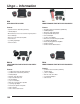
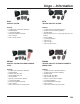
Ungo – Information K20 RK1 KEYLESS ENTRY SYSTEM REMOTE ENGINE START WITH KEYLESS ENTRY Features Features • (2) 4-Button Remote Transmitters (SAA474U) • • • • • • • • • • • • 2 Auxiliary Outputs • On-Board Relays for Door Locks and Dome Light Supervision • Horn Honk Output • Driver’s Door Unlock Priority Compatible • Comfort Closure • (+/-) Parking Light Output • Common Features (2) 4-Button Remote Transmitters (SAA474U) 2 Auxiliary Outputs Short Run / Turbo Timer Mode Compact Satellite Relay Pack
Ungo – Information S100 S670 SECURITY SYSTEM TWO-WAY SECURITY SYSTEM Features Features • • • • • • • • • • (2) 4-Button Remote Transmitters (SAA474U) 2 Auxiliary Outputs (+/-) Parking Light Output ProSecurity Programmer Compatible Common Features Common Security Features • • • • • (1) 2-Way LCD Remote Transmitter (SAA477U) (1) 4-Button Remote Transmitter (SAA474U) 3 Auxiliary Outputs On-Board Relays for Door Locks, Dome Light Supervision, and Auxiliary 1 Horn Honk Output (+/-) Parking Light Outpu
UNGO – Features and Technologies Common UNGO Features Anti-Code Grabbing Technology Individual Remote Recognition Keyless Entry* Remote Enabled Valet Hyper Blue Status LED Remote Panic Selectable Ignition Controlled Door Locks ProSecurity Starter Disable* ProSecurity Power Up Progressive Door Unlock* Dome Light Supervision Output* Trunk/Hatch Release Output* UNGO Feature Descriptions Anti-Carjacking The optional anti-carjacking system feature is designed to ensure that any unauthorized user of the vehicle
UNGO – Features and Technologies Gasoline or Diesel Vehicle Compatible Comfort Closure If programmed ON the door lock output will activate the Comfort Closure output for 20 seconds. This output will begin 200mS after the final door lock output has completed regardless of the door lock programming.
UNGO – Features and Technologies ProSecurity Power Up The ProSecurity system will store its current state of non-volatile memory. If the power is lost and then reconnected the system will recall the stored state from memory. This means if the unit is in Valet Mode and the battery is disconnected for any reason, when the battery is reconnected the unit will still be in Valet Mode.
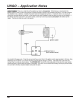
UNGO – Application Notes Obtaining Optimal Range Mounting the Extended Range Antenna: 1. Clean the mounting area with a quality glass cleaner or alcohol to remove any dirt or residue. 2. Plug the receiver/antenna cable into the receiver/antenna. 3. Mount the receiver/antenna vertically using the supplied double-sided tape. 4. Route the receiver/antenna cable to the control module and plug it into the four-pin antenna connector.
UNGO – Application Notes Obtaining a Tachometer Reference Signal The tachometer reference signal is an essential signal for the safe operation of a remote start system. This signal informs the remote start module that the vehicle has successfully started and is running. It can also determine whether the vehicle is idling at a safe RPM level. In the event the vehicles idle is racing or below safer operating level, the remote start module will shut down.
UNGO – Application Notes / Terms Voltage sensing is not recommended in areas that experience extreme cold temperatures. The resistance in the vehicles wiring increases which can cause intermittent remote start reliability. 454T: Alternator RPM Monitor The 454T Alternator RPM Monitor is for use with remote engine starts as an alternative to direct connection to the vehicle’s tachometer or fuel injector wire.
UNGO – Application Notes 131
UNGO – Application Notes 132
UNGO – Application Notes 133
UNGO – Application Notes Interfacing with Passkey 3 systems with Relays and Key 134
UNGO – Application Notes 135
Ungo – Information Bypass Modules 556U UNIVERSAL TRANSPONDER BYPASS MODULE CHRYSLER 457CW DODGE, CHRYSLER JEEP DATA INTERFACE 555C CHRYSLER DODGE JEEP TRANSPONDER BYPASS 556C 2004-UP CHRYSLER DODGE JEEP TRANSPONDER BYPASS HONDA / ACURA 556H HONDA AND ACURA TRANSPONDER BYPASS MODULE FORD 555P FORD PASSIVE ANTI-THEFT SYSTEM BYPASS MODULE 555S FORD SECURELOCK ANTI-THEFT SYSTEM BYPASS MODULE 556S FORD SECURELOCK ANIT-THEFT BYPASS MODULE GENERAL MOTORS CAN2 2005-UP GENERAL MOTORS CAN BUS DATA INTER
UNGO – Remote Start Diagnostics Remote Start Diagnostics In the event that a remote start system fails to start, or stops running after a short period of time, you can retrieve the source of the shutdown from the UNGO ProSecurity system 1. Turn the Ignition off 2. Press and hold the Override switch 3. Turn the ignition on then off 4. Release the Override switch 5. Press and release the Override switch.
UNGO – Remote Start Diagnostics ommended for any high current heavy gauge wiring. Also, if the vehicle has more than one 12-volt input wire, then connect one red wire to each. The vehicle starts, but immediately dies 1. Does the vehicle have an immobilizer? The vehicles immobilizer will cut the fuel and/or spark during unauthorized starting attempts. 2.
UNGO – Multiple Vehicle Operation Technical Information: Multiple Vehicle Operation Ungo ProSecurity remote transmitters are capable of operating multiple vehicles equipped with ProSecurity systems. This is beneficial for individuals with multiple vehicles and/or reducing the clutter on a keychain. 1. Follow the remote programming procedure for the particular ProSecurity system and delete all the remote transmitters for both vehicles. 2.
UNGO – Multiple Vehicle Operation Vehicle 1: LOCK: Arm (Lock) UNLOCK: Disarm (Unlock) LOCK & UNLOCK: Channel 2 (Auxiliary 1) Programming Vehicle 2 1. Open the door of the Vehicle 2. 2. Turn the ignition ON 3. Press the Valet/Override button 9 times and then press it one more time and hold it in. The LED will flash 9 times indicating that selection. 4. Release the Valet/Override button and turn the ignition OFF and then back ON. 5.
UNGO – Door Lock Application Guide Reverse Polarity Door Lock Systems Aftermarket Door Lock Actuators 141
UNGO – Door Lock Application Guide Vacuum Door Lock Systems The lock pulse duration my be programmed to 3.5 seconds One-Wire Door Lock System This door lock system requires a negative pulse to unlock the foors , and cutting the wire to lock the doors.
UNGO – Door Lock Application Guide Multiplexed Door Lock Systems Multiplexed door lock systems have more than one function on the same wire and require the use of different resistor values. It is necessary to use external relays any time a resistor is used. Positive Trigger Multiplexed Door Lock System Test Procedure for Multiplexed Door Lock Systems: 1. Locate the Lock/Unlock wire in the vehicle. 2. Cut the wire in half and determine the polarity of the wire. 3.
UNGO – Door Lock Application Guide Multiplexed Door Lock Systems Multiplexed door lock systems have more than one function on the same wire and require the use of different resistor values. It is necessary to use external relays any time a resistor is used. Negative Trigger Multiplexed Door Lock System Test Procedure for Multiplexed Door Lock Systems: 1. Locate the Lock/Unlock wire in the vehicle. 2. Cut the wire in half and determine the polarity of the wire. 3.
UNGO – Door Lock Application Guide Multiplexed Door Lock Systems with On-Board Relays Reverse Polarity Door Lock Systems with On-Board Relays: 145
UNGO – Door Lock Application Guide Progressive Door Lock Using Positive Door Lock Trigger 146
UNGO – Door Lock Application Guide Progressive Door Lock Using Negative Door Lock Trigger 147
UNGO – Programming Guide Technical Information Module Programming: Models: K10, K20, S670, RS10 System features can also be changed by using the ProSecurity Programmer 148
UNGO – Programming Guide K10 (Keyless Entry) Feature Default LED ON Number (Press Channel 1) 1 Active Arming 2 Chirps ON 3 Ignition Control Door Lock ON 4 Ignition Control Door Unlock ON 5 Active Locking 6 Ignition Control Dome Light ON 7 0.8 Second Door Lock Pulse 8 Double Pulse Unlock OFF 9 Security Features ON 10 Code Hopping ON Note: Factory default settings are shown BOLD.
UNGO – Programming Guide RS10 (Remote Start with Keyless Entry) Feature Default LED ON Number (Press Channel 1) 1 Engine Check ON 2 Tachometer Sensing 3 12 Minute Run Time (1)* 4 Flashing Parking Light Output 5 Cranking Time 0.6 Sec. (1)* LED OFF Setting (Press Channel 2) Engine Checking OFF Voltage Sensing 24 Min (2)*, 60 Min Run Time (3)* Constant Parking Light Output Crank Time 0.8 (2)*, 1.0 (3)*, 1.2 (4)*, 1.4 (5)*, 1.6 (6)*, 1.8 (7)*, 2.0 (8)*, 4.
UNGO – Programming Guide Technical Information Module Programming: Models: S100, S400, S660, SR1000, SR5000, SR6000 System features can also be changed by using the ProSecurity Programmer 151
UNGO – Programming Guide S100 and S400 (Security with Keyless Entry) MENU 1 Feature Number 1-1 1-2 1-3 1-4 1-5 1-6 1-7 1-8 1-9 1-10 Default LED ON (Press Channel 1) Active Arming Chirps ON Ignition Control Door Locks ON Active Locking Panic with Ignition ON Door Lock Pulse Duration 0.
UNGO – Programming Guide MENU 2 Feature Number 2-1 2-2 2-3 2-4 Default LED ON (Press Channel 1) Siren Output Constant 30-Second Siren Duration False Alarm Prevention Circuitry ON Progressive Door Trigger 2-5 2-6 2-7 2-8 2-9 2-10 Override Switch Input: 1 Pulse (1)* Open Zone Bypass Notice ON Ignition Controlled Dome Light ON Single Unlock Pulse FAD with Channel 2 ON Channel 4: Validity (1)* 2-11 Channel 5: Validity (1)* LED OFF Setting (Press Channel 2) Siren Output Pulsed 60-Second Siren Duration Fals
UNGO – Programming Guide MENU 2 Feature Number 2-1 2-2 2-3 2-4 Default LED ON (Press Channel 1) Siren Output Constant 30-Second Siren Duration False Alarm Prevention Circuitry ON Progressive Door Trigger 2-5 2-6 2-7 2-8 2-9 2-10 Override Switch Input: 1 Pulse (1)* Open Zone Bypass Notice ON Ignition Controlled Dome Light ON Single Unlock Pulse FAD with Channel 2 ON Channel 4: Validity (1)* 2-11 Channel 5: Validity (1)* MENU 3 Feature Number 3-1 3-2 3-3 3-4 3-5 3-6 3-7 3-8 3-9 3-10 3-11 3-12 Default L
UNGO – Programming Guide Note: Factory default settings are shown BOLD. Note: * The number in parentheses indicate the number of times the LED will flash. SR5000 (2-Way Remote Start with Security Combo) MENU 1 Feature Default LED ON Number (Press Channel 1) 1-1 Active Arming 1-2 Chirps ON 1-3 Ignition Control Door Locks ON 1-4 Active Locking 1-5 Panic with Ignition ON 1-6 Door Lock Pulse Duration 0.
UNGO – Programming Guide 3-9 Anti-Grind ON Anti-Grind OFF Note: Factory default settings are shown BOLD. Note: * The number in parentheses indicate the number of times the LED will flash. SR6000 (2-Way Remote Start with Security Combo) MENU 1 Feature Default LED ON Number (Press Channel 1) 1-1 Active Mode 1-2 Chirps ON 1-3 Ignition Lock ON 1-4 Ignition Unlock ON 1-5 Active Locking 1-6 Panic with Ignition ON 1-7 Door Lock Pulse Duration 0.
UNGO – Remote Programming 2-11 Channel 5: Validity (1)* MENU 3 Feature Default LED ON Number (Press Channel 1) 3-1 Engine Check ON 3-2 Tachometer Sensing 3-3 12 Minute Run Time (1)* 3-4 Flashing Parking Light Output 3-5 Cranking Time 0.6 Sec.
UNGO – Remote Programming 1-12 1-13 Code Hopping ON Channel 4 Validity (1)* MENU 2 Feature Default LED ON Number (Press Channel 1) 2-1 Engine Check ON 2-2 Tachometer Sensing 2-3 12 Minute Run Time (1)* 2-4 Flashing Parking Light Output 2-5 Cranking Time 0.6 Sec. (1)* Code Hopping OFF Latched (2)*, Latched Reset with Ignition (3)*, 30-Second Timed (4)* LED OFF Setting (Press Channel 2) Engine Checking OFF Voltage Sensing 24 Min (2)*, 60 Min Run Time (3)* Constant Parking Light Output Crank Time 0.
UNGO – Remote Programming K10, S100, S400 Channel Number 1 2 3 4 5 6 7 8 9 Function Arm/Disarm/Panic Silent Mode / Channel 2 Output Channel 3 Output Arm Only Disarm Only Panic Only Auto-Learn Single Button Arm/Disarm Configuration Auto-Learn Standard Configuration Delete All Remotes Wire Color Red/White White/Blue K20 Channel Number 1 2 3 4 5 6 7 8 Function Auto-Learn Standard Configuration Arm Only Disarm Only Silent Mode / Channel 2 Output Channel 3 Output Arm/Disarm/Panic Panic Only Delete All Remo
UNGO – Remote Programming 1 2 3 4 5 6 7 8 Auto-Learn Lock/Unlock Channel 2 Output Remote Start Turbo Timer / Short Run Turbo Timer / Short Run Rear Window Defogger Control Delete All Remotes Red/White S660 Channel Number 1 2 3 4 5 6 7 8 9 10 11 12 Function Wire Color Auto-Learn Standard Configuration Arm Only Disarm Only Silent Mode / Channel 2 Output No Function Channel 4 Channel 5 No Function No Function Arm/Disarm/Panic Panic Only Delete All Remotes Red/White Violet/Black White/Black S670 Channel
UNGO – Wiring Reference Guide 5 6 7 8 9 10 11 12 Remote Start Channel 4 Channel 5 Turbo Timer / Short Run Timer Mode Arm/Disarm/Panic Panic Only Delete All Remotes Violet/Black White/Black SR5000 Channel Number 1 2 3 4 5 6 7 8 9 10 Function Arm/Disarm/Panic Silent Mode / Channel 2 Output Remote Start Channel 4 Arm Only Disarm Only Panic Only Auto-Learn Standard Configuration Auto-Learn Single Button Arm/Disarm Configuration Delete All Remotes Wire Color Red/White Violet/Black RK1 Channel Number 1 2 3
UNGO – Wiring Reference Guide Quick Reference Wiring Diagrams: K10 (Keyless Entry) 12-Pin Harness Wire Color Orange White White/Blue Black/White Green Blue Violet Black Yellow Brown Red Red/White (-) (-) (-) (-) Polarity 500mA 200mA 200mA 200mA (-) Negative (-) Negative (+) Positive (-) 200mA (+) Positive (-) 200mA Function Ground When Armed Parking Light Output Channel 3 Auxiliary Output Dome Light Supervision Output Not Used Second Unlock Output Not Used Chassis Ground Ignition Input Horn Output Const
UNGO – Wiring Reference Guide Quick Reference Wiring Diagrams: RS10 (Remote Start with Keyless Entry) 5-Pin Harness Wire Color Blue/White Gray Brown Violet/White Black/White Polarity (-) 200mA (-) Negative (+) Positive (-) Negative Function 2nd Status Output / Rear Defroster Hood Pin Shutdown Brake Shutdown Tachometer Input Neutral Safety Shutdown 9-Pin Harness Wire Color White Black Red/White White/Red Gray/Black White/Blue Yellow Green/White Green/Black Polarity (+) 10 amp / (-) 200mA (-) Negative (-)
UNGO – Wiring Reference Guide Quick Reference Wiring Diagrams: RK1 (Advanced Remote Start with Keyless Entry) 12-Pin Harness Wire Color Orange White White/Blue Black/White Green Blue Violet Black Polarity (-) 500mA (+) 10 amp / (-) 200mA (-) Negative (-) 200mA (-) Negative Function Ground When Armed Parking Light Output Activation Input Dome Light Supervision Output Not Used Second Unlock Output Not Used Chassis Ground Brown Red Red/White (-) 200mA (+) Positive (-) 200mA Horn Output Constant Power Cha
UNGO – Wiring Reference Guide 8-Wire Harness (Relay Satellite) Purple Green Red Orange Red Pink Red/White Pink/White (+) (+) (+) (+) (+) (+) (+) (+) Positive Positive Positive Positive Positive Positive Positive Positive Starter Side Starter Wire Key Side Starter Wire High Current Constant Power Accessory 1 Output High Current Constant Power Ignition 1 Output High Current Constant Power Ignition 2 Output Quick Reference Wiring Diagrams: S100 (Security with Keyless Entry) 12-Pin Harness Wire Color Orange
UNGO – Wiring Reference Guide Quick Reference Wiring Diagrams: S400 (Security with Keyless Entry) 12-Pin Harness Wire Color Orange White White/Blue Black/White Green Blue Violet Black Yellow Brown Red Red/White Polarity (-) 500mA (+) 10 amp / (-) 200mA (-) 200mA (-) 200mA (-) Negative (-) Negative (+) Positive (-) Negative (+) Positive (+) Positive (+) Positive (-) 200mA Function Ground When Armed Parking Light Output Channel 3 Auxiliary Output Output of Domelight Supervision Relay #30 Door Trigger Input
UNGO – Wiring Reference Guide Quick Reference Wiring Diagrams: S660 (2-Way Security with Keyless Entry) 12-Pin Harness Wire Color Orange White White/Blue Black/White Green Blue Violet Black Empty Brown Red Red/White Polarity Function (-) 500mA Ground When Armed (+) 10 amp / (-) 200mA Parking Light Output No Function (-) 200mA Output of Domelight Supervision (-) Negative Door Trigger Input (-) Negative Instant Trigger Input (+) Positive Door Trigger Input (-) Negative Chassis Ground (+) Positive (+) Positiv
UNGO – Wiring Reference Guide Quick Reference Wiring Diagrams: S670 (2-Way Security with Keyless Entry) 12-Pin Harness Wire Color Orange White White/Blue Black/White Green Blue Violet Black Yellow Brown Red Red/White Polarity (-) 500mA (+) 10 amp / (-) 200mA (-) 200mA (-) 200mA (-) Negative (-) Negative (+) Positive (-) Negative (+) Positive (+) Positive (+) Positive (-) 200mA Function Ground When Armed Parking Light Output Channel 3 Auxiliary Output Output of Domelight Supervision Door Trigger Input Inst
UNGO – Wiring Reference Guide Quick Reference Wiring Diagrams: SR1000 (Security with Remote Start and Keyless Entry) 12-Pin Harness Wire Color Orange White White/Blue Black/White Green Blue Violet Black Empty Brown Red Red/White Polarity (-) 500mA (+) 10 amp / (-) 200mA (-) Negative (-) 200mA (-) Negative (-) Negative (+) Positive (-) Negative Function Ground When Armed Parking Light Output Activation Input Output of Domelight Supervision Door Trigger Input Instant Trigger Input Door Trigger Input Chassis
UNGO – Wiring Reference Guide 4-Pin Harness (Relay Satellite) Blue Orange Purple Pink (-) (-) (-) (-) 200mA 200mA 200mA 200mA Status Output 2nd Accessory Output 2nd Starter Output 3rd Ignition Output 8-Wire Harness (Relay Satellite) Purple Green Red Orange Red Pink Red/White Pink/White (+) (+) (+) (+) (+) (+) (+) (+) Positive Positive Positive Positive Positive Positive Positive Positive Starter Side Starter Wire Key Side Starter Wire High Current Constant Power Accessory 1 Output High Current Consta
UNGO – Wiring Reference Guide 5-Pin Remote Start Ribbon Harness Wire Color Red Yellow Pink Orange Purple Polarity (+) Positive (+) Positive (-) 200mA (-) 200mA (-) 200mA Function Constant Power Ignition Input 1st and 2nd Ignition Relay Output Accessory Relay Output Starter Relay Output 3-Pin Auxiliary Harness Wire Color Gray/Black LT.
UNGO – Wiring Reference Guide 5-Pin Harness Wire Color Blue/White Gray Brown Violet/White Black/White Polarity (-) 200mA (-) Negative (+) Positive (-) Negative Function 2nd Status Output / Rear Defroster Hood Pin Shutdown Brake Shutdown Tachometer Input Neutral Safety Shutdown 6-Wire Harness Wire Color LT. Green/Black Gray/Black Green/White Violet/Black White/Black LT.