Owner’s manual & Installation manual TB851P/ TB853W 8-INCH WIDE COLOUR LCD TV Clarion Co., Ltd. All Rights Reserved. Copyright © 2005: Clarion Co., Ltd. Printed in Japan / / 2005/3 (Y·Y) *TB851P/TB853W(001-cover)E 1 QZ-8000K 280-8212-00 05.2.
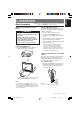
English Thank you for purchasing this Clarion TB851P/TB853W. ∗ This owner’s manual is for the TB851P/TB853W. ∗ Please read this owner’s manual completely before operating this equipment. ∗ After reading this manual, be sure to keep it in a handy place (e.g., glove compartment). ∗ Check the contents of the enclosed warranty card and keep it carefully with this manual. Contents 1. 2. 3. 4. 5. FEATURES ..........................................................................................................
WARNING For your safety, the driver should not watch the TV or operate the controls while driving. Watching the TV while driving is prohibited by law in some countries. Also, while driving, keep the volume to a level at which external sounds can still be heard. 1. This unit is a precision mechanism. Even if trouble occurs, never open the case, disassemble the unit, or lubricate the rotating parts. Superimpose Appears for 7 seconds when the media source was switched to TV mode.
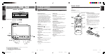
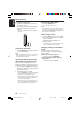
/ Remote Control 4. PART NAMES Note: • Except for the following buttons, the remote control button names are the same as the buttons on the main unit. Operating Buttons Note: • Be sure to read this chapter while referring to the front diagrams in chapter “3. CONTROLS” on page 5 (unfold). [OPEN/CLOSE] [SRC] button • Press to turn on the power. • Press and hold for 2 seconds or longer to turn off the power.
/ Remote Control 4. PART NAMES Note: • Except for the following buttons, the remote control button names are the same as the buttons on the main unit. Operating Buttons Note: • Be sure to read this chapter while referring to the front diagrams in chapter “3. CONTROLS” on page 5 (unfold). [OPEN/CLOSE] [SRC] button • Press to turn on the power. • Press and hold for 2 seconds or longer to turn off the power.
WARNING For your safety, the driver should not watch the TV or operate the controls while driving. Watching the TV while driving is prohibited by law in some countries. Also, while driving, keep the volume to a level at which external sounds can still be heard. 1. This unit is a precision mechanism. Even if trouble occurs, never open the case, disassemble the unit, or lubricate the rotating parts. Superimpose Appears for 7 seconds when the media source was switched to TV mode.
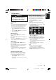
Note: Be sure to read this chapter referring to the front diagrams in chapter “3. CONTROLS” on page 5 (unfold). Basic Operation Opening and adjusting the LCD panel WARNING • To prevent the battery from going dead, operate this unit with the engine running if possible. • When the LCD panel is operating, be careful not to get your hands or finger caught between the panel and main unit or the vehicle instrument panel. • Do not move the LCD panel by hand. Raising the LCD panel 1. Press the [OPEN] button.
English Basic Operation ● To adjust the slide position 1. Hold down the [TILT] button and release it when a beep is heard. The LCD panel slides forward or backward. This adjusted slide position is stored in memory. ∗ There are 3 adjustable positions available on this panel. Turning power ON or OFF 1. Press the [POWER] button. Use to turn the power on or off. Note: • The LCD panel does not store away even if the power is turned off.
WARNING For your safety, the driver should not watch or operate TV while driving. Viewing and operating the TV while driving are prohibited by law in some countries. Watching TV Note: • For your safety, the TB851P/TB853W has a safety function which turns off the picture when the car is moving, so only the audio can be heard. The picture can only be watched when the car is stopped and the parking brake is applied. 1. Press the [SRC] button and select the TV mode.
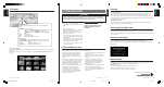
English TV Operation Auto store function Selecting the screen size This function automatically stores a received broadcast as a preset channel. 1. Press the [P.LIST] button for 2 second or more. The broadcast stations are automatically stored in the memory in order starting from the currently received station. 2. To cancel, press the [P.LIST] button again. Notes: • Poor signal conditions might cause a channel with no station to be stored in the memory.
To view video images: ● How to connect to video Use the VTR mode to transfer output audio or images such as video. Video out/VTR input cable CCA-623-500 (sold separately) Gray Yellow Black Yellow Black Red Black White Left Right To audio OUT terminal To video OUT terminal ● Select the video mode 1. Press the [SRC] button to select VTR1 or VTR2. The setting shifts in the sequence shown below, each time the [SRC] button is pressed.
English Operating with an external device ● Viewing video images 1. Press the [SRC] button to select VISUAL1 or VISUAL2. The setting shifts in the sequence shown below, each time the [SRC] button is pressed. TV ➔ VTR1 ➔ VTR2 ➔ VISUAL1 ➔ VISUAL2 ➔ TV ➔ ... Video from the external device connected to the video in terminal (visual input 1 or visual input 2) appears on the screen. Notes: • See the instruction manual of the external device to be connected to find out how to operate that external device.
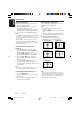
How to set (Main screen during TV mode) 1. Press the [ADJ] button to display the ADJUST mode screen. Each press of the [ADJ] button switches the ADJUST mode screen. 2. Press the [w] or [z] button to select the item to set. 3. Press the [A] or [D] button to select the setting value. 4. Press the [ENT] button to return to the original screen.
English Changing the settings (ADJUST mode) Adjust the screen image quality Screen image quality Adjust the screen luminance, brightness, hue and color level to view video at your own preferred image quality. • You can only make this adjustment in TV/VTR/ VISUAL modes while the vehicle is stopped. • Only the screen luminance and brightness can be adjusted in modes other than TV/VTR or when driving in TV/VTR mode.
Select the FM modulator and RCA audio output levels ∗ The factory setting is at “HIGH”. • In TV mode, the FM modulator output is at “HIGH”, even when set to “LOW” during TV mode. • Not displayed during VISUAL mode. 1. Select “AUDIO LEV” on the ADJ_EXTERNAL screen. 2. Press the [A] or [D] button to select the “HIGH” or “LOW”. • HIGH : Outputs signal at same level as the audio from the car radio. • LOW : Lowers the output level to -6dB. (Set to LOW when audio is distorted when set at HIGH.
English Changing the settings (ADJUST mode) Select PAL or NTSC This setting allows you to select the video system for input to the VTR. This can be separately set for VTR 1, VTR 2, VISUAL 1 and VISUAL 2. ∗ The factory setting is at “AUTO”. • This setting can be made in the VTR and VISUAL modes. 1. Select “PAL/NTSC” on the ADJ_OTHER screen. 2. Press the [A] or [D] button and select “PAL”, “NTSC” or “AUTO”.
English 6. TROUBLESHOOTING ■ If you think that something is wrong with your unit, check the following points before requesting servicing. Problem No image display. Cause Action The parking brake is not set. Check that the parking brake is set. Vehicle is moving. No video is displayed on the unit while driving. Park the vehicle before playing this unit. (Set the parking brake.) No TV mode (function). To watch TV, press the source button and check that the TV screen is now set. Monitor is at OFF.
Screen size: 7-inch wide type (176.4 mm Width ✕ 99.2 mm Height) Display method: Transmission type TN LCD Drive method: TFT(thin-film transistor) active matrix driving Pixels: 336,960 (1440 ✕ 234) TV Tuner Tuning system: PLL synthesizer system Reception channels: • TB851P VHF: CCIR 2 to 12 ch (47 to 230 MHz) NEW ZEALAND 1 to 11 ch (44 to 230 MHz) AUSTRALIA 0 to 12ch (45 to 230 MHz) CHINA 1 to 12ch (48.
Installation and Wire connection manual ■ Contents 1. 2. 3. 4. 5. 6. 7. 8. 9. BEFORE STARTING ............................................................... PACKAGE CONTENTS ........................................................... GENERAL CAUTIONS ............................................................ CAUTIONS ON INSTALLATION .............................................. INSTALLING THE MAIN UNIT ................................................. REMOVING THE MAIN UNIT ...........................
English 3. GENERAL CAUTIONS 1. Do not open the case. There are no user serviceable parts inside. If you drop anything into the unit during installation, consult your dealer or an authorized CLARION service centre. 2. Use a soft, dry cloth to clean the case. Never use a rough cloth, thinner, benzine, or alcohol, etc. For tough dirt, apply a little cold or warm water to a soft cloth and wipe away the dirt gently. 4. CAUTIONS ON INSTALLATION 1.
English 5. INSTALLING THE MAIN UNIT ■ Universal Mount 1. Place the universal mounting bracket into the instrument panel, use a screwdriver to bend each stopper of the universal mounting bracket inward, then secure the stopper as shown in Figure 6. 2. Wire as shown in Section 8. 3. Insert the main unit into the universal mounting bracket until it locks in place. 4. Mount the outer escutcheon so that all the hooks are locked. Notes: 1) Some car models require special mounting kits for proper installation.
English ■ Fixed Mount (TOYOTA, NISSAN and other ISO/DIN equipped vehicles) This unit is designed for fixed installation in the dashboard. If the vehicle is equipped with a factory-installed radio, install the main unit with the parts and screws marked (∗). (Figure 8) If the vehicle is not equipped with a factoryinstalled radio, obtain an installation kit to install the main unit with the following procedure. 1. Remove the screws from both side of the main unit.
1. After the rear of the main unit has been secured by the method shown in Figure 6 unfasten the special screw. 2. Remove the outer escutcheon. 3. Insert the hook plate between the spring and the universal mounting bracket, fit tab B of the spring into hole A of the hook plate, then English 6. REMOVING THE MAIN UNIT pull the main unit out by the hook plate. (Insert both the right and left edges of the hook plate.) (Figure 9) Note: Do not dispose of the hook plate.
English 8. WIRE CONNECTION TV antenna input Connect to 4-line diversity antenna (sold separately). Black Red Black White Black Yellow (Right) Audio out (Left) Visual input 1 Gray Yellow Visual input 2 ∗1 Video out/VTR input cable CCA-623-500(sold separately) Red Audio input (right) White Audio input (left) Yellow video input Yellow video output Connect the vehicle radio antenna jack. Connect to the antenna terminal of the car audio (with radio).
English ■ Connecting the Accessories • Connection to the CCD camera for vehicle For detailed information, refer to the instruction sheet or manual for the CCD camera. Notes: • A power supply box (sold separately) is required for connecting the main unit and the CCD camera. • The power supply box for camera CAA147 cannot be used. Please use the CAA188 instead.
English 9. SAMPLE SYSTEMS ■ Sample System 1 CeNET cable DVD Receiver Yellow TV antenna input CeNET CD changer Black Yellow Visual input 1 Yellow Visual input 2 Gray VTR etc.
Owner’s manual & Installation manual TB851P/ TB853W 8-INCH WIDE COLOUR LCD TV Clarion Co., Ltd. All Rights Reserved. Copyright © 2005: Clarion Co., Ltd. Printed in Japan / / 2005/3 (Y·Y) *TB851P/TB853W(001-cover)E 1 QZ-8000K 280-8212-00 05.2.