installation_rev3.
installation_rev3.qxd 7/26/99 6:07 PM Page 3 Table of Contents 1. 2. 3. 4. 5. 6. 7. 8. 9. 10. 11. 12. 13. 14. Before You Begin . . . . . . . . . . . . . . . . . . . . . . . . . . . . . . . . . . . . . . . . . . . . . . . . . . . . . . . . .Page 1 Installation Tips . . . . . . . . . . . . . . . . . . . . . . . . . . . . . . . . . . . . . . . . . . . . . . . . . . . . . . . . . .Page 2 Mounting Components Main Unit . . . . . . . . . . . . . . . . . . . . . . . . . . . . . . . . . . . . . . . . . .
installation_rev3.qxd 7/26/99 6:07 PM Page 1 Before You Begin 1. Be sure to read the manual thoroughly before beginning the installation to ensure a proper understanding of the MS8200 / MS8300 and its functions. 2.
installation_rev3.qxd 7/26/99 6:07 PM Page 2 Installation Tips 1. Use a Volt / Ohm meter to test all wires. Do not use a test light. 2. Good power and ground connections are essential for proper operation. 3. Route all wires from the engine compartment to the interior of the vehicle through a grommet and use electrical tape and split loom tubing for protection. 4. When adding optional accessories such as door locks, window modules, etc.
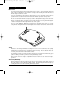
installation_rev3.qxd 7/26/99 6:07 PM Page 3 Mounting Components Main Unit The main unit should be mounted in the interior of the vehicle. Do not mount the main unit in the engine compartment. For maximum security, avoid mounting the main unit where it will be easily accessible to a thief. If you are mounting the unit under the dash board, be sure to mount the unit as high as possible and in a location where it will not interfere with the operation of the pedals.
installation_rev3.qxd 7/26/99 6:07 PM Page 4 Extended Range Antenna (MS8300) Mount the extended range antenna to the front windshield behind the rear view mirror for best operation. Be sure that this area is clean and free of any metallic window tint film. In certain vehicles such as those equipped with a heated windshield or a built-in windshield defroster, the antenna should be mounted on a rear or side window. Mount the antenna at least 2 inches below the roof line.
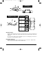
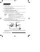
installation_rev3.qxd 7/26/99 6:07 PM Page 5 Mounting For Shock Sensitivity Only Mounting For Shock and Motion Sensitivity Motion Sensitivity Front/Rear Side to Side Least Best Good Good Good Good Best Least Position Override Switch Mount the Override Switch in a location near the driver where it is easily accessible but not plainly visible. Plug the blue override switch connector into the blue 2-pin socket on the main unit.
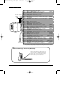
installation_rev3.qxd 7/26/99 6:07 PM Page 6 Space Shield III (MS8300) Mount the Space Shield III facing upward in a central location within the vehicle. For optimum performance, avoid mounting the sensor under or facing metal objects or support structures as they will alter the shape of the sensor’s protection zones. Also, be sure to mount the sensor in a location where items such as coins or coffee cups cannot be placed on top of the sensor.
installation_rev3.
installation_rev3.qxd 7/26/99 6:07 PM Page 8 Wiring Description 18-Pin Main Harness Pin 1 - BLACK: Ground. Connect to a solid chassis ground. Be sure to use a ring connector of proper size. Scrape away the paint at the grounding point. Pin 2 - YELLOW: Door Trigger (+12v) input Connect to positive door switch circuit. This circuit, commonly found in Ford vehicles, will show +12v when the door is open.
installation_rev3.qxd 7/26/99 6:07 PM Page 9 Pin 6 - WHITE: Door Trigger (-) input Connect to negative door switch circuit. This circuit will show ground (-) when the door is open. Pin 7 - YELLOW/green: Auxiliary Function 4 (-) output Provides a negative output to activate a relay. The wire provides output for as long as the transmitter button is pressed.
installation_rev3.qxd 7/26/99 6:07 PM Page 10 When latched or timed operation is selected, the output will reset (turn off) each time the system is armed or disarmed. Pin 15 - ORANGE/blue: Alarming / Horn Honk (-) output Provides a negative output when the system is triggered to activate a relay. The output is selectable for continuous or pulsed operation. See Programming Switches.
installation_rev3.qxd 7/26/99 6:07 PM Page 11 3-Pin Door Lock Harness Pin 1 - WHITE/green: Door Lock (-) / Door Unlock (+) Pin 2 - **not used** Pin 3 - WHITE/blue: Door Unlock (-) / Door Lock (+) These wires can be directly connected to negative and positive triggered door lock systems. For Voltage Reversal systems and After-market actuators, add relays. For further information, see Door Lock Diagrams.
installation_rev3.qxd 7/26/99 6:07 PM Page 12 Jumper and Switch Settings Jumper Selections Cancel Auto Rearm. Disables the Automatic Rearm Feature. On = Auto Rearm Disabled Off = Auto Rearm Enabled Parking Light Polarity. Selects the polarity (+/-) for the output of the on-board Parking Light relay. Pin 1 + Pin 2 = positive Pin 2 + Pin 3 = negative Dome Light Polarity. Selects the polarity (+/-) for the output of the on-board Illuminated Entry/Exit relay.
installation_rev3.qxd 7/26/99 6:07 PM Page 13 Accessing the Jumpers and Switches Using a flathead screwdriver, carefully press in on the access tabs on the sides of the case until the hooks release. Take care not to push the tabs in too far or they may break. Once you have made your selections, close the case by aligning the top and button halves of the case, making sure that the tabs are over their mounting holes.
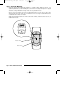
installation_rev3.qxd 7/26/99 6:07 PM Page 14 Remote Transmitters Using the Remote Transmitters Button 1 LED Button 2 Mode Button Each system comes with 2 Remote Transmitters, pre-programmed to Arm and Disarm the system with chirp confirmation using Button 1. The Mode Button will change function of both Button 1 and Button 2 each time it is pressed. When the Arm/Disarm Button is pressed together with any other Transmitter Button, the systems Chirp confirmation setting will be reversed.
installation_rev3.qxd 7/26/99 6:07 PM Page 15 during Programming, Logic Sensor II Adjustment, Space Shield III Adjustment, Real Time System Verification or any other system set-up function. The Buttons used to control those features will remain as they are described in this manual, regardless of how the Transmitter is set up to arm and disarm the system.
installation_rev3.qxd 7/26/99 6:07 PM Page 16 Adding a New Transmitter into the System 1. Turn on the ignition. 2. Press and hold the Override switch. • The status LED will turn on red. 3. Within 5 seconds: Continue holding the Override switch and Press Transmitter Button 1* For remote arming with chirp confirmation. --- or --Release the Override switch and Press Transmitter Button 1* For remote arming without chirp confirmation.
installation_rev3.qxd 7/26/99 6:07 PM Page 17 Programming System Initialization and Default Reset Following this procedure will set all System Programming Parameters to factory default settings. 1. Turn on ignition. 2. After 4 seconds, press and hold Buttons 1 and 2 together for 5 seconds. The siren will emit one long chirp, indicating that the reset signal was received. 3. Turn ignition off. • • • • • All System Programming parameters are now set to factory default settings.
installation_rev3.
installation_rev3.qxd 7/26/99 6:07 PM Page 19 • After 5 seconds, the Transmitter’s LED will begin to flash rapidly, indicating the signal to turn off the Logic Sensor II is being transmitted. • The siren will emit three chirps confirming the signal has been received and will ignore the Logic Sensor II until next time the system is armed. 4. Audible Tamper Alert Report. When Audible Tamper Alert is selected, the siren will chirp to indicate which zone had triggered the system, upon disarming.
installation_rev3.qxd 7/26/99 6:07 PM Page 20 10. Auxiliary Function 2 - Momentary / Latched / Timed Operation. (resets with arm and disarm) Selects between Momentary, Latched, or Timed output for Aux. 2. When Momentary operation is selected, the system will provide an output for as long as the Transmitter button is held. When Latched operation is selected, the system will provide an output that turns on when the transmitter button is pressed and turns off when the transmitter button is pressed again.
installation_rev3.qxd 7/26/99 6:07 PM Page 21 Logic Sensor II Because of its advanced design, the Logic Sensor II can be set for Shock and Motion detection or Shock detection only, simply by the way the sensor is mounted. See Mounting Components. Adjustment The shock and motion sensitivity of the Logic Sensor II are set independently, using the Remote Transmitter. For shock, there are 12 levels of sensitivity. For motion, there are 8 levels of sensitivity. Level 1 is off for both shock and motion.
installation_rev3.qxd 7/26/99 6:07 PM Page 22 The sensitivity of the Logic Sensor II’s Light Impact Response can also be adjusted. There are two settings for Warn Away, High and Low. The default setting is High. To change the setting, see Programming. Space Shield III The Space Shield III is a dual zone proximity sensor that uses high frequency radar signals to detect the presence of moving objects within a defined area. For more information, see Mounting Components.
installation_rev3.qxd 7/26/99 6:07 PM Page 23 When the minimum or maximum sensitivity levels have been reached, the siren will emit 4 quick chirps. 5. Once you are satisfied with the Interior zone sensitivity setting, press the Mode Button, then Button 2 to begin adjusting the Exterior zone. • The siren will chirp 4 times, the Exterior zone can be adjusted. 6. Test the Exterior zone sensitivity.
installation_rev3.qxd 7/26/99 6:07 PM Page 24 Real Time Installation Verification This feature allows the installer to quickly and effectively check all aspects of the installation. To enter Real Time System Verification: 1. 2. 3. 4. Enter the vehicle. Close the vehicle doors, hood, and trunk. Turn on the ignition. Within 4 seconds, press the Mode button then press and hold Button 1 for 5 seconds. • The siren will emit one long chirp. • The Starter Kill and the Armed outputs will activate. 5.
installation_rev3.qxd 7/26/99 6:07 PM Page 25 • During output testing, each function will stay active for as long as the transmitter button is held. After you have finished testing, turn off the ignition key to exit Real Time Installation Verification.
installation_rev3.qxd 7/26/99 6:07 PM Page 26 Seven Event Trigger History This feature allows you to recall, from the system’s memory, the events (zones) that have triggered the system during the last seven times the system was armed. This is especially useful in diagnosing sensors that are causing the system to trigger and need adjustment. To enter Trigger History: 1. Turn on the ignition. 2. Open the door. 3. After 4 seconds, press Button 1 on the Remote Transmitter. • The siren will chirp once.
installation_rev3.
installation_rev3.