VMA6492 6.
OWNER’S MANUAL WARNING! THE CLARION VMA6492 LCD MONITOR IS DESIGNED FOR REAR SEAT PASSENGER VIEWING ONLY. THIS PRODUCT IS NOT INTENDED FOR VIEWING BY THE DRIVER WHILE THE VEHICLE IS IN MOTION SINCE SUCH USE MAY DISTRACT THE DRIVER OR INTERFERE WITH THE DRIVER’S SAFE OPERATION OF THE VEHICLE AND MAY RESULT IN SERIOUS INJURY OR DEATH. SUCH USE MAY ALSO VIOLATE STATE LAW.
VMA6492 6.4” TFT LCD Monitor PRECAUTIONS: • This monitor is intended for use in DC 12V, negative ground vehicles. • Do not operate the monitor in ways other than described in this guide. Doing so may cause damage and void the warranty. • Be careful not to run down the car’s battery while using a multimedia system with the engine stopped. Doing so may damage the vehicle’s battery or the multimedia system. • Do not disassemble or modify the monitor. Doing so may damage it and void the warranty.
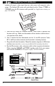
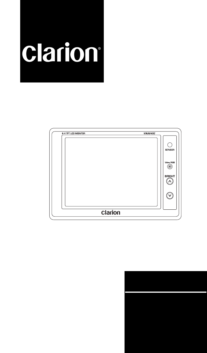
OWNER’S MANUAL DESCRIPTION OF PICTURE ADJUSTMENT: BRIGHTNESS: To adjust the picture brightness, use the Brightness UP and DOWN buttons 3 located on the front panel of the VMA6492. Press and hold the UP button to increase the picture brightness. Press and hold the DOWN button to decrease the picture brightness (see page 2 for button locations). VIEWING ANGLE: To adjust the viewing angle gently tilt the cabinet to the desired position.
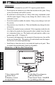
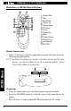
VMA6492 6.4” TFT LCD Monitor monitor will accept a video signal from any video source with composite video output. The Infrared (IR) sensor will work directly with a Clarion TTX001 or VDH9600 using the IR extension cable provided (see Application starting on page 5 for details). INSTALLATION 1. Look over the vehicle for a monitor location. Each vehicle is different and locations will vary. Make sure the monitor will not interfere with the driver’s safe operation of the vehicle. 2.
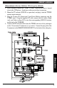
OWNER’S MANUAL APPLICATIONS: (With the VDH9600, TTX001 and the FM100S) 1. Pick a location to mount the TTX001 TV tuner. Typically the tuner is located close to the VCR player. Avoid areas with excessive heat or moisture. 2. Mount the TV antenna (ZCB-303 or equivalent) and plug it into the TTX001 antenna input connector. 3. Plug the 16-pin A/V Output and 2-pin Power Molex connector into the TTX001 tuner.
VMA6492 6.4” TFT LCD Monitor 5. 6. 7. 8. 9. er. Connect the other jack end of the Y-connector into the IR extension cable coming from the VMA6492 monitor. Plug the video RCA from the VMA6492 into the LINE OUT video connection on the rear of the player. Plug the provided audio RCA cable into the L/R LINE OUT audio connections. Connect the power wires from the VMA6492, TTX001, and the power wires of the VDH9600 together. Remove the vehicle’s radio.
OWNER’S MANUAL mounting location. Plug each cable into the monitor. Mount the monitor using four (4) M4x8 mm machine screws (machine screws are provided with the mounting brackets). 4. Run the IR extension, video RCA, and power wires to the TTX001 location and plug each into the TTX001 tuner (see the figure below for more details). 5. Pick a location to mount the WH100/200 transmitter, plug in the L/R audio RCAs and power connector. Run the L/R RCAs and power wire to the TTX001’s location.
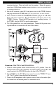
VMA6492 6.4” TFT LCD Monitor DESCRIPTION OF RC300 REMOTE BUTTONS: 1 Number Pad 2 Skip 3 Erase/Write 4 Volume Up 5 Volume Down 6 TV/Video 7 Power 8 Channel Up 9 Mute 0 Channel Down q Picture Select w Auto Memory e TV/CATV BATTERY INSTALLATION: • Insert 2 AAA batteries into the compartment located on the back of the unit, observing the proper polarity. RC300 REMOTE NOTE: Each time the batteries are changed, the remote channels must be reprogramed.
OWNER’S MANUAL TROUBLESHOOTING: Symptom Cause System does not Fuse is blown. work. Power wires are not connected. The picture has The signal condishadows when con- tion is poor. nected to the TTX001. Solution Replace external fuse with the same value. Check the wire connections and connect it properly. This may due to signals reflected off buildings, mountains, etc. Check again in a different place and direction. The picture has There may be interstripes or spots ference signals.
PUT TITLE HERE FCC STATEMENT This equipment has been tested and found to comply with the limits for a Class B digital device, pursuant to Part 16 of the FCC Rules. These limits are designed to provide reasonable protection against harmful interference in a residential installation. This equipment generates, uses, and can radiate radio frequency energy and, if not installed and used in accordance with the instructions, may cause harmful interference to radio communications.