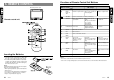
VRX610 Owner’s manual & Installation manual Mode d’emploi et manuel d’installation Manual de instrucciones y de instalación VRX610 6.5” MONITOR & FM/AM RADIO WITH CD/MD CHANGER CONTROL • MONITEUR DE 6,5 POUCES ET RADIO FM/AM AVEC COMMANDE DE CHANGEUR DE CD/MD • MONITOR DE 6,5-PULGADAS Y RADIO FM/AM CON MANDO PARA EL CAMBIADOR DE CD/MD Clarion Co., Ltd. All Rights Reserved. Copyright © 2001: Clarion Co., Ltd.
Thank you for purchasing the Clarion VRX610. ∗ This owner’s manual is for the VRX610. ∗ Please read this owner’s manual in its entirety before operating this equipment. ∗ After reading this manual, be sure to keep it in a handy place (e.g., glove compartment). ∗ Check the contents of the enclosed warranty card and keep it carefully with this manual. ∗ This manual includes the operating procedures of the CD changer, MD changer, TV tuner and digital sound processor (DSP) connected via the CeNET cable.
4. MODE DISPLAY 1. PRECAUTIONS The Color LCD Display and the Information Panel on the main unit show the following displays, providing information about the mode and functions operated. ! For your safety, the driver should not watch the TV or operate the controls while driving. Please note that watching and operating the TV while driving are prohibited by law in some countries. Also, while driving, keep the volume to a level at which external sounds can be heard.
2. CONTROLS // COMMANDES COMMANDES // CONTROLES CONTROLES CONTROLS Main unit / Unité principale / Unidad principal With the Display closed / Avec l`afficheur fermé / Con el visualisador cerrado 3. NOMENCLATURE JOYSTICK Operation Note: • Many settings/procedures have to be performed by using the JOYSTICK ¡. Be sure to read this chapter in order to operate it properly. Names of Buttons Note: • Be sure to read this chapter referring to the front diagrams of chapter “2. CONTROLS” on page 5 (unfold).
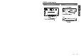
RADIO mode display COLOR LCD DISPLAY INFORMATION PANEL MAIN SUB VRX610 9
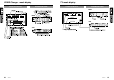
CD/MD Changer mode display TV mode display COLOR LCD DISPLAY INFORMATION PANEL COLOR LCD DISPLAY INFORMATION PANEL MAIN MAIN SUB SUB 10 VRX610 VRX610 11
Functions of Remote Control Unit Buttons 5. REMOTE CONTROL Mode Button When the panel is open FUNC Switches among Radio, CD changer, MD changer and TV. ¢ BAND DISC UP TOP Switches reception band. 25 VOLUME Increases and decreases volume (in all modes). § SEARCH Moves preset channels up and down. ¶ PLAY/PAUSE No function. • MUTE Turns mute on and off. ª ISR ISR on and off. º DISP MONI Turns on and off the monitor. ⁄ PS/AS SCN Preset scan.
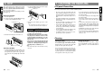
6. DCP The control panel can be detached to prevent theft. When detaching the control panel, store it in the DCP (DETACHABLE CONTROL PANEL) case to prevent scratches. We recommend taking the DCP with you when leaving the car. 7. CAUTIONS ON HANDLING 2. Lock the DCP/Operation Panel at the upper center until a click is heard. POWER button LCD panel/Generalities For a longer service life, be sure to read the following cautions. • Removing the DCP 1. Turn the power off. 2.
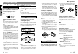
Basic Operations 8. OPERATIONS Basic Operations Note: Be sure to read this chapter referring to the front diagrams of chapter “2. CONTROLS” on page 5 (unfold). CAUTION When the unit is turned on, starting and stopping the engine with its volume raised to the maximum level may harm your hearings. Be careful about adjusting the volume. Note: • Use this unit after starting the engine.
Basic Operations When the panel is closed: Each time you press the Z-EHCR button 9, the tone effect changes in the following order: “Z-EHCR 1” ➜ “Z-EHCR 2” ➜ “Z-EHCR 3” ➜ “Z-EHCR OFF” ➜ “Z-EHCR 1”... When the panel is open: 1. Press the A-M button & to change into the AUDIO-MODE display. 2. Operate the JOYSTICK ¡ upward or downward to select “Z-EHCR”. Press the ENT at the center of the JOYSTICK ¡ to change into the Z-enhancer selecting display. 3.
Radio Operations Radio Operations FM reception ® For enhanced FM performance the tuner includes signal actuated stereo control, Enhanced Multi AGC, Impulse noise reduction curcuits and Multipath noise reduction circuits. Changing the reception area This unit is initially set to USA frequency intervals of 10kHz for AM and 200kHz for FM. When using it outside the USA, the frequency reception range can be switched to the intervals below.
CD Changer Operations CD changer functions When an optional CD changer is connected through the CeNET cable, this unit controls all CD changer functions. This unit can control a total of 2 changers (MD and/or CD). Press the FUNC button 1 and select the CD changer mode to start play. If 2 CD changers are connected, press the FUNC button 1 to select the CD changer for play. ∗ If “NO MAG” appears in the display, insert the magazine into the CD changer.
MD Changer Operations MD changer functions When an optional MD changer is connected through the CeNET cable, this unit controls all MD changer functions. This unit can control a total of 2 changers (MD and/or CD). Press the FUNC button 1 and select the MD changer mode to start play. If 2 MD changers are connected, press the FUNC button 1 to select the MD changer for play. MD Changer Operations Notes: • When the disc title is within 16 characters, the title is scrolled immediately.
TV Operations TV functions When an optional TV tuner is connected through the CeNET cable, this unit controls all TV tuner functions. To watch TV requires a TV tuner. WARNING For your safety, the driver should not watch the TV or operate the controls while driving. Please note that watching and operating the TV while driving are prohibited by law in some countries.
Rear Vision Camera TV Operations Adjusting the brightness and tone of color Notes: • This operation is available only when the car is stopped and the parking brake is applied. • This function is not available when the display is stored. • The HUE setting can be adjusted only when the NTSC mode is selected. 1. Press the ADJ button * to switch to the adjustment selection display. 2. Operate the JOYSTICK ¡ upward or downward to select the option “MONI ADJ” (by moving the cursor). 3.
Other Functions Always turning on the button illumination on the operation panel Note: • The following operation is enabled when the panel is open. The button illumination on the operation panel when the display is turned upward, can be switched between “ON” and “OFF”. ● “ON”: Button illumination on the operation panel turns on for 5 seconds; ● “OFF” : Button illumination is always on when the power is turned on; 1. When the panel is open, press the ADJ button £ to show the adjustment selection display. 2.
DSP operations DSP operations DSP control function Operations common to each mode If the DSP (DPH7500z/7700z), sold separately, is connected to this unit using the CeNET cable, all the functions of the DSP can be controlled. Output adjustment of auto loudness, subwoofer and playback band ∗ When the DSP is connected, an external amplifier is required. ∗ DSP control can all be operated only when the panel is open.
DSP operations Standard mode/G.EQ operations Note: • The adjustment made in standard mode is not reflected in the adjustment in professional mode. Respectively, the adjustment made in professional mode is not reflected in the adjustment in standard mode. G.EQ effect ON/OFF ∗ The factory default setting is “ON”. 1. Press the A-M button & to show the AUDIOMODE display. 2. Operate the JOYSTICK ¡ upward or downward to select “EQ ON/OFF”. “ON” and “OFF” items are displayed in the menu bar. 3.
DSP operations DSP operations 7. To set a title of the stored USER pattern, operate the JOYSTICK ¡ rightward or leftward to select “TITLE” and press the ENT at the center of the JOYSTICK ¡ to change into the Title Input display. ∗For title inputting method, refer to the section “Entering titles”. 8. Operate the JOYSTICK ¡ rightward or leftward to select “MENU” and press the ENT at the center of the JOYSTICK ¡ to change into the AUDIO-MODE display.
DSP operations ∗ By pressing the PRESET buttons # 1 to 6 for 2 seconds or longer in the P.EQ adjusting display, the P.EQ pattern can be stored in the USER memory. 9. IN CASE OF DIFFICULTY Problem 7. To set a title of the stored USER pattern, operate the JOYSTICK ¡ rightward or leftward to select “TITLE” and press the ENT at the center of the JOYSTICK ¡ to change into the Title Input display. ∗For title inputting method, refer to the section “Entering titles”. 8.
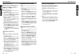
Measure A radio wave may not reach sufficiently due to obstruction of mountains or buildings. Check it again at a place where a radio wave can be received properly. The TV tuner has a double or triple image. Bad receiving condition It may be under the influence of radio wave reflected by mountains or buildings. Check it again after changing place or direction. The TV tuner has spots or stripes in the image.
11. SPECIFICATIONS FM Tuner General Frequency Range: 87.9 MHz to 107.9 MHz Usable Sensitivity: 11 dBf 50dB Quieting Sensitivity: 17 dBf Alternate Channel Selecitivity: 75 dB Stereo Separation(1 kHz): 35 dB Frequency Response(+/-3 dB): 30 Hz to 15 kHz Power source voltage: 14.4 V DC (10.8 to 15.6 V allowable) Ground: Negative Current consumption: 4.
3. 1. Do not open the case. There are no user serviceable parts inside. If you drop anything into the unit during installation, consult your dealer or an authorized CLARION service centre. 4. 5. GENERAL CAUTIONS 2. Use a soft, dry cloth to clean the case. Never use a rough cloth, thinner, benzine, or alcohol, etc. For tough dirt, apply a little cold or warm water to a soft cloth and wipe off the dirt gently. CAUTIONS ON INSTALLATION 1.
■ Fixed Mount (TOYOTA, NISSAN and other ISO/DIN equipped vehicles) This unit is designed for fixed installation in the dashboard. If the vehicle is equipped with a factory-installed radio, install the main unit with the parts and screws marked (∗). (Figure 8) If the vehicle is not equipped with a factory-installed radio, obtain an installation kit to install the main unit in the following procedure. 1. Remove the screws from both side of the main unit.
7. 8. CAUTIONS ON WIRING 1. Be sure to turn the power off before wiring. 2. Be particularly careful where you route the wires. Keep them well away from the engine, and exhaust pipe, etc. Heat may damage the wires. 3. If the fuse should blow, check to see if the wiring is correct. If it is, replace the fuse with a new one with the same amperage rating as the original. 4. When any fuse is to be replaced, pull out the fuse (15A) at the rear of the main unit and put in a new one (Fig.10).
■ Connecting the Accessories • SAMPLE SYSTEMS Connection to the external amplifier The external amplifier can be connected to the AUDIO 4CH. OUTPUT terminal (RCA pin jack) on the main unit. In other words, it can be connected provided the DSP is connected. • 9. ■ Sample System 1 Connection to the security camera for vehicle The rear vision camera for vehicle can be connected to the system expansion terminal on the main unit.
■ Sample System 2 MAIN UNIT VRX610 ∗ AMP built-in, Line out 4channel output. DPH7500z/7700z ∗ To enable the correct input, it is necessary to configure the VRX610 as described on page 29. ∗ To enable the correct input, it is necessary to configure the VRX610 as described on page 26. CDC655z/655Tz/1255z RDC655z/655Tz/1255z DCZ615/CDZ616 ∗ When DSP is connected, external amplifier is required. ∗ When two CD changers or MD changers are connected, CCA-519 is required.
Memo 54 VRX610