VRX6671z Owner’s manual & Installation manual Mode d’emploi et manuel d’installation Manual de instrucciones y de instalación VRX6671z 6.5” MONITOR & FM/AM RADIO WITH CD/MD CHANGER CONTROL • MONITEUR DE 6,5 POUCES ET RADIO FM/AM AVEC COMMANDE DE CHANGEUR DE CD/MD • MONITOR DE 6,5-PULGADAS Y RADIO FM/AM CON MANDO PARA EL CAMBIADOR DE CD/MD Clarion Co., Ltd. All Rights Reserved. Copyright © 2000: Clarion Co., Ltd.
Thank you for purchasing the Clarion VRX6671z. ∗ This owner’s manual is for the VRX6671z. ∗ Please read this owner’s manual in its entirety before operating this equipment. ∗ After reading this manual, be sure to keep it in a handy place (e.g., glove compartment). ∗ Check the contents of the enclosed warranty card and keep it carefully with this manual. ∗ This manual includes the operating procedures of the CD changer, MD changer, TV tuner and digital sound processor (DSP) connected via the CeNET cable.
4. MODE DISPLAY 1. PRECAUTIONS The Color LCD Display and the Information Panel on the main unit show the following displays, providing information about the mode and functions operated. ! For your safety, the driver should not watch the TV or operate the controls while driving. Please note that watching and operating the TV while driving are prohibited by law in some countries. Also, while driving, keep the volume to a level at which external sounds can be heard.
2. CONTROLS // COMMANDES COMMANDES // CONTROLES CONTROLES CONTROLS Main unit / Unité principale / Unidad principal With the Display closed / Avec l`afficheur fermé / Con el visualisador cerrado 3. NOMENCLATURE JOYSTICK Operation Note: • Many settings/procedures have to be performed by using the JOYSTICK ¡. Be sure to read this chapter in order to operate it properly. Names of Buttons Note: • Be sure to read this chapter referring to the front diagrams of chapter “2. CONTROLS” on page 5 (unfold).
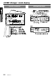
RADIO mode display COLOR LCD DISPLAY INFORMATION PANEL MAIN SUB VRX6671z 9
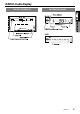
CD/MD Changer mode display COLOR LCD DISPLAY INFORMATION PANEL MAIN SUB 10 VRX6671z
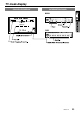
TV mode display COLOR LCD DISPLAY INFORMATION PANEL MAIN SUB VRX6671z 11
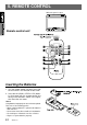
5. REMOTE CONTROL When the panel is open Remote control unit WIDE 1 Inserting the Batteries 1. Turn the remote control unit over, then slide the rear cover in the direction of the arrow. 2. Insert the AA (SUM-3, IECR-6/1.5V) batteries that came with the remote control unit facing in the directions shown in the figure, then close the rear cover. Notes: Using batteries improperly can cause them to explode. Take note of the following points: • When replacing batteries, replace both batteries with new ones.
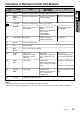
Functions of Remote Control Unit Buttons Mode Button CD changer MD changer Radio TV £ FUNC Switches among Radio, CD changer, MD changer and TV. ¢ BAND DISC UP TOP Switches reception band. 25 VOLUME Increases and decreases volume (in all modes). § SEARCH Moves preset channels up and down. ¶ PLAY/PAUSE No function. • MUTE Turns mute on and off. ª ISR ISR on and off. º DISP MONI Turns on and off the monitor. ⁄ PS/AS SCN Preset scan. When pressed and held for 2 seconds: Auto store.
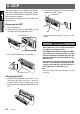
6. DCP The control panel can be detached to prevent theft. When detaching the control panel, store it in the DCP (DETACHABLE CONTROL PANEL) case to prevent scratches. We recommend taking the DCP with you when leaving the car. 2. Lock the DCP/Operation Panel at the upper center until a click is heard. POWER button Removing the DCP 1. Turn the power off. 2. Deeply push in the DCP RELEASE lever 6 to release the DCP/Operation Panel. DCP/RALEASE lever 3. Press the power button 1 to turn on the power .
7. CAUTIONS ON HANDLING LCD panel/Generalities For a longer service life, be sure to read the following cautions. • • • • • • Be sure to store the LCD panel inside the main unit when parking the car outdoors for long period of time. The LCD panel will operate properly in a temperature range of 0 to 60°C. Don’t allow any liquids on the set from drinks, umbrellas etc. Doing so may damage the internal circuitry. Do not disassemble or modify the set in any way. Doing so may result in damage.
8. OPERATIONS Basic Operations Note: Be sure to read this chapter referring to the front diagrams of chapter “2. CONTROLS” on page 5 (unfold). CAUTION When the unit is turned on, starting and stopping the engine with its volume raised to the maximum level may harm your hearings. Be careful about adjusting the volume. Note: • Use this unit after starting the engine.
Basic Operations • If a title has been input, it is shown in the SUB display. If no title has been input, “---------” appears in the display. To input a title, refer to the subsection “Entering titles” in “Other Functions” section. • Some special characters of the title, will not be displayed on the Information Panel of the DCP. In this case, those characters will only be left blank. 3. To store the Color LCD display ¥ in the source unit, turn it to the horizontal position until a click is heard.
Basic Operations When the panel is closed: Each time you press the Z-EHCR button 9, the tone effect changes in the following order: “Z-EHCR 1” ➜ “Z-EHCR 2” ➜ “Z-EHCR 3” ➜ “Z-EHCR OFF” ➜ “Z-EHCR 1”... When the panel is open: 1. Press the A-M button & to change into the AUDIO-MODE display. 2. Operate the JOYSTICK ¡ upward or downward to select “Z-EHCR”. Press the ENT at the center of the JOYSTICK ¡ to change into the Z-enhancer selecting display. 3.
Basic Operations Turning on/off the loudness The loudness effect emphasizes the bass and treble to create a natural sound tone. When you are listening to music at a low volume, it is recommended to use the loudness effect. ∗ This function is enabled only when the panel is open. 1. Press the A-M button & for 1 second or longer to select Loudness ON. The “LD” indicator lights in the display. 2. Press the A-M button & for 1 second or longer to select Loudness OFF. The “LD” indicator goes off.
Radio Operations FM reception ® For enhanced FM performance the tuner includes signal actuated stereo control, Enhanced Multi AGC, Impulse noise reduction curcuits and Multipath noise reduction circuits. Changing the reception area This unit is initially set to USA frequency intervals of 10kHz for AM and 200kHz for FM. When using it outside the USA, the frequency reception range can be switched to the intervals below.
Radio Operations Manual memory Instant station recall (ISR) 1. Press the BAND button % and select the desired band. (FM or AM) 2. Select the desired station with seek tuning, manual tuning, or preset tuning. 3. Press and hold one of the PRESET buttons # for 2 seconds or longer to store the current station into preset memory. Instant station recall is a special radio preset that instantly accesses a favorite radio station at a touch of a button. The ISR function even operates with the unit in other modes.
CD Changer Operations CD changer functions When an optional CD changer is connected through the CeNET cable, this unit controls all CD changer functions. This unit can control a total of 2 changers (MD and/or CD). Press the FUNC button 1 and select the CD changer mode to start play. If 2 CD changers are connected, press the FUNC button 1 to select the CD changer for play. ∗ If “NO MAG” appears in the display, insert the magazine into the CD changer.
CD Changer Operations Fast-forward/Fast-backward Repeat play ● Fast-forward Press and hold the right side of the SEARCH button 2 for 1 second or longer. ● Fast-backward Press and hold the left side of the SEARCH button 2 for 1 second or longer. The repeat play continuously plays the current track. This function continues automatically until it is cancelled or the mode is changed. 1. Press the RPT button 7, to make repeat play starts. “RPT” lights in the display. 2.
MD Changer Operations MD changer functions When an optional MD changer is connected through the CeNET cable, this unit controls all MD changer functions. This unit can control a total of 2 changers (MD and/or CD). Press the FUNC button 1 and select the MD changer mode to start play. If 2 MD changers are connected, press the FUNC button 1 to select the MD changer for play. Notes: • When the disc title is within 16 characters, the title is scrolled immediately.
MD Changer Operations Scan play Random play The scan play locates and plays the first 10 seconds of each track on a disc automatically. This function continues on the disc until it is cancelled or the mode is changed. The random play selects and plays individual tracks on the disc in no particular order. This function continues automatically until it is cancelled or the mode is changed. 1. When you press the RDM button 8, random play starts. “RDM” lights in the display. 2.
TV Operations TV functions When an optional TV tuner is connected through the CeNET cable, this unit controls all TV tuner functions. To watch TV requires a TV tuner. WARNING For your safety, the driver should not watch the TV or operate the controls while driving. Please note that watching and operating the TV while driving are prohibited by law in some countries.
TV Operations Manual memory Setting the TV diver 1. Select the desired station with seek tuning, manual tuning or preset tuning. 2. Press and hold one of the PRESET buttons # for 2 seconds or longer to store the current station to that preset memory. ∗ This function is enabled only when the panel is open. ∗ Normally use the TV diver with the “ON” position. Auto store Auto store selects 6 TV stations automatically and stores each one into a preset memory.
TV Operations Adjusting the brightness and tone of color Notes: • This operation is available only when the car is stopped and the parking brake is applied. • This function is not available when the display is stored. • The HUE setting can be adjusted only when the NTSC mode is selected. 1. Press the ADJ button * to switch to the adjustment selection display. 2. Operate the JOYSTICK ¡ upward or downward to select the option “MONI ADJ” (by moving the cursor). 3.
Rear Vision Camera Monitoring the rear vision camera The rear vision camera can be connected to this unit. For the power supply of the camera, mount the power box sold separately (CAA-147). Notes: • This function is not available when the display is stored. Operation of External Visual Devices (VISUAL Mode) External visual devices such as DVD and VTR devices can be connected to the DIN 8-pin terminal, and the image and sound can then be played using VISUAL mode.
Other Functions Always turning on the button illumination on the operation panel Note: • The following operation is enabled when the panel is open. The button illumination on the operation panel when the display is turned upward, can be switched between “ON” and “OFF”. ● “ON”: Button illumination on the operation panel turns on for 5 seconds; ● “OFF” : Button illumination is always on when the power is turned on; 1. When the panel is open, press the ADJ button £ to show the adjustment selection display. 2.
Other Functions Clock Adjustment 1. Press the ADJ button * to display the adjustment selection display. 2. Move the JOYSTICK ¡ up or down to select CLOCK, then press ENT at the center of the JOYSTICK ¡ to display the clock adjustment display. 3. Move the JOYSTICK ¡ left or right to select HR or MIN, then move the JOYSTICK ¡ up or down to adjust the time. ∗ The time is displayed in 12-hour format. 4.
DSP operations DSP control function Operations common to each mode If the DSP (DPH7500z), sold separately, is connected to this unit using the CeNET cable, all the functions of the DSP can be controlled. Output adjustment of auto loudness, subwoofer and playback band ∗ When the DSP is connected, an external amplifier is required. ∗ DSP control can all be operated only when the panel is open. DSP functions There are 2 modes available in DPH7500z, easy mode and professional mode.
DSP operations 4. After adjustment (setting), operate the JOYSTICK ¡ rightward or leftward to move the cursor to “MENU” and press the ENT at the center of the JOYSTICK ¡ to return to the adjustment selection display. 5. Press the ADJ button * again to return to the STANDARD display. Selecting the easy mode or the professional mode ∗ The factory default setting is “EASY”. 1. Press the ADJ button * to switch to the adjustment selection display. 2.
DSP operations Easy mode/G.EQ operations Note: • The adjustment made in easy mode is not reflected in the adjustment in professional mode. Respectively, the adjustment made in professional mode is not reflected in the adjustment in easy mode. G.EQ effect ON/OFF ∗ The factory default setting is “ON”. 1. Press the A-M button & to show the AUDIOMODE display. 2. Operate the JOYSTICK ¡ upward or downward to select “EQ ON/OFF”. “ON” and “OFF” items are displayed in the menu bar. 3.
DSP operations 8. Operate the JOYSTICK ¡ rightward or leftward to select “MENU” and press the ENT at the center of the JOYSTICK ¡ to change into the AUDIO-MODE display. Easy mode/DSP operations DSP effect ON/OFF ∗ The factory default setting is “ON”. 1. Press the A-M button & to show the AUDIOMODE display. 2. Operate the JOYSTICK ¡ upward or downward to select “DSP ON/OFF”. “ON” and “OFF” items are displayed in the menu bar. 3.
DSP operations 7. To set a title of the stored USER pattern, operate the JOYSTICK ¡ rightward or leftward to select “TITLE” and press the ENT at the center of the JOYSTICK ¡ to change into the Title Input display. ∗For title inputting method, refer to the section “Entering titles”. 8. Operate the JOYSTICK ¡ rightward or leftward to select “MENU” and press the ENT at the center of the JOYSTICK ¡ to change into the AUDIO-MODE display. Professional mode/S.
DSP operations JOYSTICK ¡ for 2 seconds or longer to store the adjusted S.EQ pattern to the USER memory. ∗ By pressing the PRESET buttons # 1 to 6 for 2 seconds or longer in the S.EQ adjusting display, the S.EQ pattern can be stored in the USER memory. 7. To set a title of the stored USER pattern, operate the JOYSTICK ¡ rightward or leftward to select “TITLE” and press the ENT at the center of the JOYSTICK ¡ to change into the Title Input display.
DSP operations ∗ By pressing the PRESET buttons # 1 to 6 for 2 seconds or longer in the P.EQ adjusting display, the P.EQ pattern can be stored in the USER memory. 7. To set a title of the stored USER pattern, operate the JOYSTICK ¡ rightward or leftward to select “TITLE” and press the ENT at the center of the JOYSTICK ¡ to change into the Title Input display. ∗For title inputting method, refer to the section “Entering titles”. 8.
9. IN CASE OF DIFFICULTY Problem Cause Measure Power does not turn on. (No sound is produced.) Fuse is blown. Replace with a fuse of the same amperage. If the fuse blows again, consult your store of purchase. Incorrect wiring. Consult your store of purchase. Nothing happens when buttons are pressed. The microprocessor has malfunctioned due to noise, etc. Turn off the power, then press the RELEASE lever 6 and remove the DCP. Press the RESET button for about 2 seconds with a thin rod.
TV Problem Measure A radio wave may not reach sufficiently due to obstruction of mountains or buildings. Check it again at a place where a radio wave can be received properly. The TV tuner has a double or triple image. Bad receiving condition It may be under the influence of radio wave reflected by mountains or buildings. Check it again after changing place or direction. The TV tuner has spots or stripes in the image.
10. ERROR DISPLAYS If an error occurs, one of the following displays is displayed. Take the measures described to eliminate the problem. MD CHANGER CD CHANGER CD Error Display Cause Measure ERROR 2 A CD is caught inside the CD deck and is not ejected. This is a failure of CD deck’s mechanism and consult your store of purchase. ERROR 3 A CD cannot be played due to scratches, etc. Replace with a non-scratched, non-warped-disc.
11. SPECIFICATIONS FM Tuner Frequency Range: 87.9 MHz to 107.
VRX6671z Installation and Wire connection manual ■ Contents 1. 2. 3. 4. 5. 6. 7. 8. 9. 1. BEFORE STARTING..................................................43 PACKAGE CONTENTS...............................................43 GENERAL CAUTIONS................................................44 CAUTIONS ON INSTALLATION.................................44 INSTALLING THE MAIN UNIT....................................45 REMOVING THE MAIN UNIT.........................................47 CAUTIONS ON WIRING..........