Owner’s manual & Installation manual Mode d’emploi et manuel d’installation Manual de instrucciones y de instalación XC6210 XC6410 XC AMPLIFIERS AMPLIFICATEURS XC AMPLIFICADORES XC
INTRODUCTION English The Clarion XC6210 (two-channel amplifier) and XC6410 (four-channel amplifier) incorporate the following features: • Conformal Coated PC Board that resists mold, mildew and moisture damage. • Pulse-Width Modulated (PWM) MOSFET power supply for maximum performance with minimal distortion. • Remote turn-on with "soft start" muting to prevent turn-on "thump".
DESCRIPTION English The XC6210 and XC6410 use a PWM regulated power supply for superior sound and output wattage. All of the connections and controls for the XC6210 and XC6410 are conveniently labeled and located on one side of the amplifier. To ensure the best possible electrical connections, the power, speaker and RCA inputs are corrosion resistant. An additional benefit of the XC6410 is the ability to create a 2, 3, or 4 configuration.
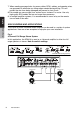
Red Black Red White Blue White Speaker level adaptor cable RCA inputs are fully balanced and can accept RCA pre amp levels. With speaker level adaptor cable the inputs will accept speaker levels. (High Level RCA Speaker Adapter Included) English XC6210 Owner’s Manual 1. 2. 3. 4. 5. 6. 7. 8. 9. 10. 11.
• Input Gain Controls: Allow you to match the source unit’s output voltage to achieve maximum output from the amplifier. The amplifier can accommodate input levels from virtually any head unit with an input range of 200mV to 6.0V. Regarding high-level input: Please use included high-level to RCA adapters. Owner’s Manual • Input Select (XC6410 Only) [2CH BB/2CH/4CH]: 2CH BB: Uses CH1/2 inputs and has output from all 4 channels with Bass Boost. 2CH: Uses CH1/2 inputs and has output from all 4 channels.
XC6410 - Electrical Connection Remote Turn-On English Owner’s Manual F U S E CH1 Speaker (+) CH2 Speaker (-) CH1 Speaker (-) CH2 Speaker (+) CH3 Speaker (+) CH4 Speaker (-) CH3 Speaker (-) CH4 Speaker (+) XC6210 - Electrical Connection 6 XC6210/XC6410
INSTALLATION This section suggests Mounting and Wiring Precautions for installing the Clarion XC6210 or XC6410. If you do not posses the necessary tools and installation experience, do not attempt to install these amplifiers. Instead, contact your local Clarion audio dealer to perform the installation. English MOUNTING PRECAUTIONS Owner’s Manual Prior to mounting the amplifier, make sure it is safe to mount the amplifier in desired location.
English 7. When creating passage holes for power cables, RCA’s cables, and speaker wires, use grommets to eliminate any sharp edges created during drilling. This will protect the wire from being damaged and prevent a short circuit. 8. Extra cable can cause signal loss and act as an “antenna” for noise. Use only high-quality RCA cables that are no longer than necessary. 9. In multiple amplifier systems, it is recommended to use a relay on the remote turn-on lead of the radio.
Fig. 5 2-Channel High-Pass, 2-Channel Low-Pass In this 4-channel system, the XC6410 drives a pair of component speakers and a pair of subwoofers. Note the switch settings.
Fig. 6 2-Channel Stereo System with Low-Pass Bridged Mono Channel The XC6410 can also be used to drive a pair of component speakers and a single mono subwoofer using one set of RCA’s. Note the switch settings.
Fig. 7 2-Channel High Power System Speakers The XC6410 can be set up as a 2-channel high power amplifier to drive a pair of speakers (stereo). Note the switch settings.
XC6210 WIRING AND APPLICATIONS The Clarion XC6210 2-channel audio amplifier can be used in a variety of system applications. Here are a few examples to help plan your own installation. English Fig. 8 2-Channel Full-Range Stereo System In this application, the amplifier is used in stereo and drives two full-range speakers. Note the switch settings.
Fig. 9 Subwoofer Stereo System In this application, the amplifier is used to drive two subwoofers. Note the switch settings. English Owner’s Manual CH1 Subwoofer 2Ω or 4Ω CH2 Subwoofer 2Ω or 4Ω Fig. 10 Bridged - Mono Subwoofer System In this application the amplifier is bridged for mono operation to drive a subwoofer. Note the switch settings.
ADJUSTING THE INPUT GAIN CONTROL After completing the installation, follow these steps to set the Input Gain Control. English 1. Set Input Gain Control to MIN (counterclockwise). 2. Power on source. Set all Tone or Equalization Controls to “flat” positions and set Loudness off. 3. Play a CD, set the Source Volume Control to 75% of max level. 4. Slowly adjust the Input Gain Control of amplifier. Stop when you hear a slight distortion of audio.
TROUBLESHOOTING Problem No Audio. Amplifier not powering on. (LED turned off) Solution English Remote turn-on voltage. Check remote connections at amplifier and source unit. Blown amplifier fuse. Replace with new fuse (same rating). Owner’s Manual Power wires not connected. Check power and ground wiring at amplifier and at battery. Speaker leads shorted. Check speaker continuity to ground, it should not show a common ground. Speakers not connected or are blown.
Problem Amplifier fuse keeps blowing. Solution Incorrect wiring or short circuit. Review installation and check all wiring connections. English Problem Whining or ticking noise in the audio with engine on. Owner’s Manual Solution Amplifier is picking up alternator noise or radiated noise. Lower input gain; move audio cables away from power wires.
PRODUCT SPECIFICATIONS 20Hz ~ 20kHz Variable 50Hz ~ 500Hz, *(x10, 500Hz ~ 5kHz) 200mV ~ 6.0V 600W (300W x 2) 85W x 4 @1.0% THD 125W x 4 @1.0% THD 250W x 2 @1.0% THD 30A x 2 222 mm x 55 mm x 174.2 mm 8.74 in x 2.17 in x 6.86 in English Owner’s Manual XC6410 Frequency Response Crossover Frequency (Low, High, Full) Low Level Input Sensitivity Max. Power Output @4Ω RMS Power Output @4Ω RMS Power Output @2Ω RMS Bridged Power Output @4Ω Fuse Dimensions (WxHxD) Power Output: 85W x 4RMS [4Ω @ 14.
Clarion Corporation of America All Rights Reserved.